 Revision of Ver.7.4.1
 Revision of Ver.7.4.1
Function
Select the structural frame type (braced/unbraced) with respect to the global X- and Y-directions. Select the auto-calculation option for the effective buckling length factors for column members.
Call
From the Main Menu select Design > General Design Parameter > Definition of Frame.
From the Menu tab of the Tree Menu select Design > General Design Parameter > Definition of Frame.
Entry
The following dialog box is used to enter the data:

 Definition of Frame
Define the type of structural frame.
X-Direction of Frame
Select Unbraced | Sway or Braced | Non-sway frame in the global X-direction
(Default = Unbraced | Sway).
Y-Direction Frame
Select Unbraced | Sway or Braced | Non-sway frame in the global Y-direction
(Default = Unbraced | Sway).
Design Type
When members in a 3-D structure are designed, a Design Type is selected to account for only the forces in the selected plane to design the members as a 2-D frame.
3 - D: Design is carried out while accounting for all the member forces in the 3-D frame.
X - Z Plane: Design is carried out while accounting for only the member forces in the GCS X-Z plane as a 2-D frame.
Y - Z Plane: Design is carried out while accounting for only the member forces in the GCS Y-Z plane as a 2-D frame.
X - Y Plane: Design is carried out while accounting for only the member forces in the GCS X-Y plane as a 2-D frame.
Note
This option may become handy when a structure with continuity in one direction
is to be designed as a 2-D frame.
Auto Calculate Effective
Length FactorsSelect if the effective buckling length factors are to be automatically calculated.
Revision of Ver.7.4.1
Note Auto calculation procedure for effective length factor
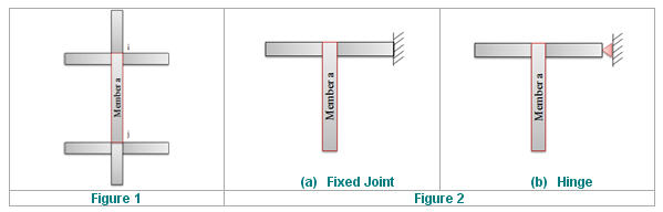
(1) Calculate the stiffness, S (=EI/L), of the members which are connected to the ‘Member a’ as shown in the figure 1 below. If the joint of the flexural member is fixed or hinged as shown in the figure 2 below, the stiffness, S, is modified as below.
Fixed joint: S = (1/1.5)* EI/L
Hinge: S= (1/2.0)* EI/L
Where, E: Modulus of elasticity
I: Moment of inertia of section
L: Span length of flexural member measured from center to center of joints
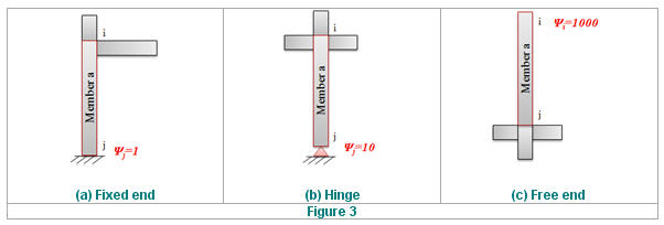
(2) Calculate Ψ and Ψ. Ψ is the ratio of Σ(EI/lc) of compression members and Σ(EI/l) of flexural members in a plane at one end of a compression member. As shown in the figure 3 below, if the end of the compression member is fixed or hinged, Ψ is taken as 1 or 10 respectively. If the compression member is not connected to any flexural member, Ψ is taken as 1000.
(3) Calculate the solution, X, in the stability equation below.
Braced / Nonsway frames
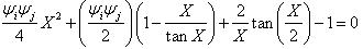
Unbraced / Sway frames
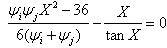
Where, Ψ: Ratio of Σ(EI/lc) of compression members to Σ(EI/l) of flexural members in a plane at one end of a
compression member.
(4) Calculate the effective length factor, K

[Reference: "Steel structures" (1982), Ballio and Mazzolani]
.jpg) : Enter the selection
and close the dialog box.
: Enter the selection
and close the dialog box.
.jpg) : Do not enter the selection
and close the dialog box.
: Do not enter the selection
and close the dialog box.