To avoid the process of clicking several times for invoking a function, MIDAS has incorporated a new feature known as “Command Line”. This feature is similar to the one in AutoCAD and improves the efficiency of modeling and analysis. By just typing a simple abbreviated command in the Command Line, the program will invoke the dialog box or direct the user to the related function. This will speed up the process of generating an analytical model and improve its accuracy in design.
The shortcut commands for the Command Line are saved in a shortcutkey. cmd file in a text format, which is located in the User Folder. For generating a frequently used command, the user can create or modify commands in this text file.
Command Line
How to use the Command Line
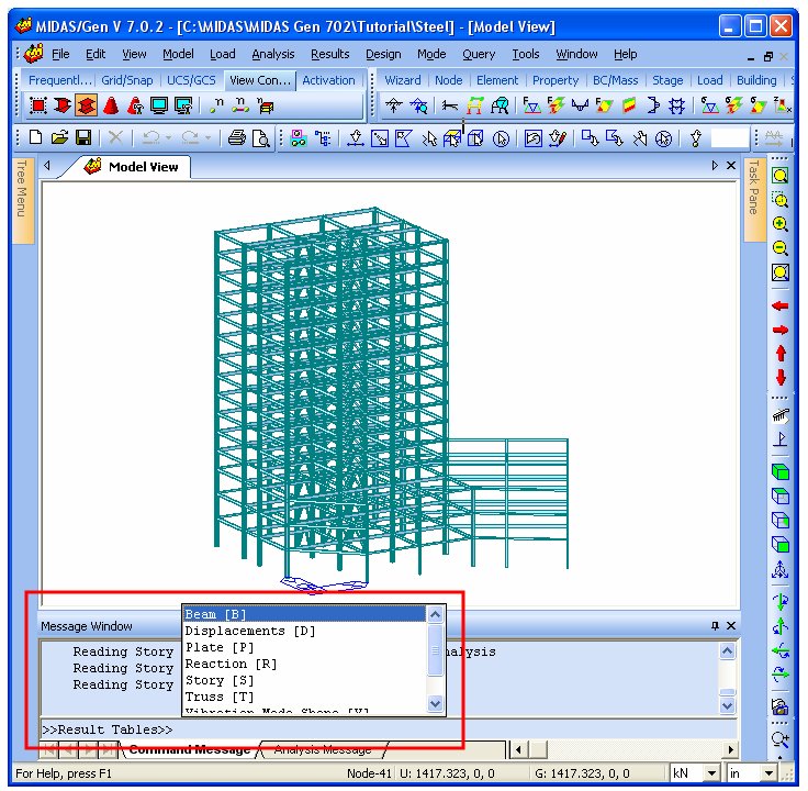
1. Click on the Command Line or click on an arbitrary point in Model View and then Press the Space Bar. The user will then see the cursor blinking on the command line.
2. Enter a shortcut key that is indicated in the shortcutkey.cmd file. There are two kinds of keys that can be specified – the Command Key and the Group Key. Command Key is the key for invoking any menu or function. Group Key is the key for invoking a Command Group. If all menus of MIDAS/Gen need to be defined then there will be some difficulty in defining shortcuts with one or two characters. Also, if the number of characters is increased, then the efficiency of using the shortcut keys will decrease. For this reason, MIDAS has introduced the tree structure of folders which is similar to the one in Microsoft Windows. Several keys can be grouped together and the same command in another group can be specified to be the same key. The shortcut key does not need to be designated in a specific group and several groups can exist in one group.
[Examples]
1) Using the Command Key:
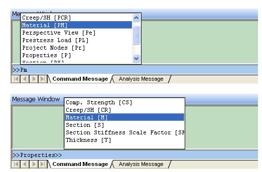
By inputting ‘PM’ in the command line ‘Model >Properties > Material’ menu can be invoked.
2) Using the Group Key:
Since, ‘P’ represents a group key for ‘Properties’ and ‘M’ represents a command key for ‘Material’, typing ‘PM’ will invoke the material properties dialog box. Another option is to type the characters separately. If ‘P’ is typed then the program will invoke the Properties group and a pop-up list will appear showing the commands that can be chosen. If ‘M’ is typed, then the program will invoke the Material properties dialog box, which is the same as typing ‘PM’.
Shortcut Keys input using the Command Line.
3. When any character is inputted in the Command Line a pop-up list containing the sub-commands appears. The user can either type the command as specified by the character, or use the direction keys to highlight the command and select it by either pressing the space bar or Enter key. The user can also select by clicking the command with the mouse.
4. After the command is executed, the Command Line reverts back to the default state.
5. The user can delete the inputted command by pressing the backspace key.
How to create a Command Key
All the information relating to the Command Keys is saved in a shortcutkey.cmd file which is located in C:\> Program Files> MIDAS> MIDAS Gen> User folder. By modifying this file the user can customize the shortcut keys for frequently used commands.
The format of the shortcutkey.cmd file is as follows. Usually one command key and one Group Key are included in one line.
Key, Display Text/Group Path, Type, Menu Path or Group Name/Path
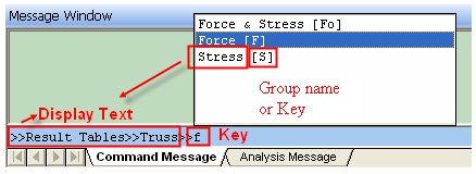
Key: Shortcut Key to invoke the applicable dialog box.
Display Text: The text that is displayed when inputting the corresponding key.
Group Path: If the corresponding command key is a key inside a group, then the user inputs the Group path. When inputting the Group path, the user should use the name of the group.
Type: Type of Keys
C: Command Key.
G: Group Key. Selects the Command Group
L: Selects the lower grade group. This is a shortcut key to select other groups that are included in the group which is active.
Menu Path: If the Key type is ‘C’ then the user should define the path of the menu to be performed. The path should be inputted based on Main Menu and ‘…’ included in the menu is ignored. Writing with upper case or lower case doesn’t matter.
Group Name: If the Key Type is ‘G’ then the user inputs the name of the group.
Group Path: If the Key type is ‘L’, then the user inputs the path of the upper graded group which the selected lower grade group is included. When inputting the path of the Group the user should use the name of the group.
[Example]
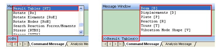
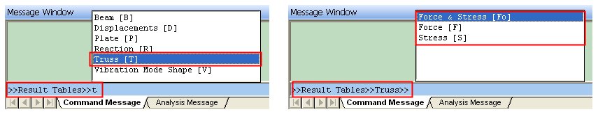
1. RT, Result Tables, G, RT
2. T, RT > Truss, G, RTT
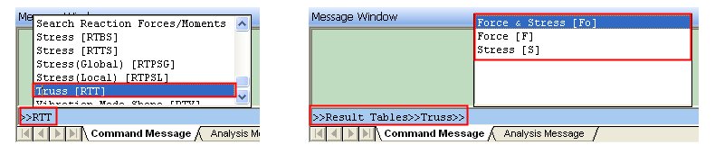
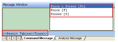
3. RTT, Truss, L, RT > Truss
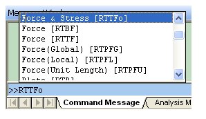
4. Fo, RT > RTT > Force & Stress, C, Results > Result Tables > Truss > Force & Stress
5. RTTF, Force, C, Results > Result Tables > Truss > Force
1. This creates a Command Group of ‘RT’. When the user types ‘RT’ on the Command Line then a pop-up list will appear and the Result Table will be selected. The lower grade group pop-up list will also be displayed.
2. This defines a group name ‘RTT’, which is a lower grade of ‘RT’ and the group key as ‘T’ is specified. In this case, in the path 'RT > Truss', ‘RT’ does not refer to a Group Key but is a Group name.
The user selects the Result table by typing ‘RT’ and the Truss Group by typing ‘T’ again. Then a pop-up list of Command Keys which is included to the Truss Group will display.
3. This defines a ‘L’ type key ‘RTT’, which is included in Result Table (RT). This key enables the user to select the Truss Group at once. If the user types ‘RTT’, then the group path of RT>truss can be selected.
4. This defines the command key ‘Fo’. This is a command key for the Force and Stress menu which is a lower grade group of Truss. The command key ‘Fo’, which performs the path ‘Results > Result Tables > Truss > Force & Stress’, should be defined in the group of Result Table (RT) > Truss(T).
To perform this key, the user should assign the key in the ‘Result Table (RT)>Truss’ group.
5. This defines a Command Key ‘RTTFo’, which performs the path ‘Results > Result Tables > Truss > Force & Stress’. Since this Command Key is not included in any Group, it can be typed in the default Command Line.
NOTE
1. If there are group keys that are duplicated, then the program will read the upper Group that is defined in the shortcutkey.cmd file.
2. If the Command Key is duplicated, then the program will read the latest Command that is defined in the shortcutkey.cmd file.
3. The user should specify the Group Name precisely to designate the path of the Group.
4. The user can press the space bar when the Command Line is defaulted to display the keys included in the Upper Groups or Command Keys that are not included.
5. The user cannot use the Command Line function during analysis.
Command List (contents of shortcutkey.cmd)
Str, Structure Type, C, Model>Structure Type
C, Create, G, C
N, C > Create Nodes, C, Model > Nodes > Create Nodes
CN, Create Nodes, C, Model > Nodes > Create Nodes
E, C > Create Elements, C, Model > Elements > Create Elements
CE, Create Elements, C, Model > Elements > Create Elements
D, Delete, G, D
N, D > Delete Nodes, C, Model >Nodes >Delete
DN, Delete Nodes, C, Model >Nodes >Delete
E, D > Delete Elements, C, Model > Elements > Delete
DE, Delete Elements, C, Model > Elements > Delete
T, Translate, G, T
N, T > Translate Nodes, C, Model > Nodes > Translate
TN, Translate Nodes, C, Model > Nodes > Translate
E, T > Translate Elements, C, Model > Elements > Translate
TE, Translate Elements, C, Model > Elements > Translate
Ro, Rotate, G, Ro
N, Ro > Rotate Nodes, C, Model > Nodes > Rotate
RoN, Rotate Nodes, C, Model > Nodes > Rotate
E, Ro > Rotate Elements, C, Model > Elements > Rotate
RoE, Rotate Elements, C, Model > Elements > Rotate
Mi, Mirror, G, Mi
N, Mi > Mirror Nodes, C, Model > Nodes > Mirror
MiN, Mirror Nodes, C, Model > Nodes > Mirror
E, Mi > Mirror Elements, C, Model > Elements > Mirror
MiE, Mirror Elements, C, Model > Elements > Mirror
Di, Divide, G, Di
N, Di > Divide Nodes, C, Model > Nodes > Divide
DiN, Divide Nodes, C, Model > Nodes > Divide
E, Di > Divide Elements, C, Model > Elements > Divide
DiE, Divide Elements, C, Model > Elements > Divide
Me, Merge, G, Me
N, Me > Merge Node, C, Model > Nodes > Merge
MeN, Merge Node, C, Model > Nodes > Merge
E, Me > Merge Elements, C, Model > Elements > Merge
MeE, Merge Elements, C, Model > Elements > Merge
Ren, Renumbering, G, Ren
N, Ren > Renumbering, C, Model > Nodes > Renumbering
RenN, Renumbering, C, Model > Nodes > Renumbering
E, Ren > Renumbering, C, Model > Elements > Renumbering
RenE, Renumbering, C, Model > Elements > Renumbering
Pr, Project Nodes, C, Model > Nodes > Project
I, Intersect Elements, C, Model > Elements > Intersect
E, Extrude Elements, C, Model > Elements > Extrude
Ch, Change Element Parameters, C, Model > Elements > Change Element Parameters
P, Properties, G, P
M, P > Material, C, Model > Properties > Material
PM, Material, C, Model > Properties > Material
S, P > Section, C, Model > Properties > Section
PS, Section, C, Model > Properties > Section
CR, P > Creep/SH, C, Model > Properties > Time Dependent MAterial(Creep/Shrinkage)
PCR, Creep/SH, C, Model > Properties > Time Dependent MAterial(Creep/Shrinkage)
SF, P > Section Stiffness Scale Factor, C, Model > Properties > Section Stiffness Scale Factor
PSF, Section Stiffness Scale Factor, C, Model > Properties > Section Stiffness Scale Factor
T, P > Thickness, C, Model > Properties > Thickness
PT, Thickness, C, Model > Properties > Thickness
CS, P > Comp.Strength, C, Model > Properties > Time Dependent MAterial(Comp. Strength)
PCS, Comp.Strength, C, Model > Properties > Time Dependent MAterial(Comp. Strength)
B, Boundaries, G, B
S, B > Supports, C, Model > Boundaries > Supports
BS, Supports, C, Model > Boundaries > Supports
R, B > Beam End Release, C, Model > Boundaries > Beam End Release
BR, Beam End Release, C, Model > Boundaries > Beam End Release
O, B > Beam End Offsets, C, Model > Boundaries > Beam End Offsets
BO, Beam End Offsets, C, Model > Boundaries > Beam End Offsets
RL, B > Rigid Link, C, Model > Boundaries > Rigid Link
BRL, Rigid Link, C, Model > Boundaries > Rigid Link
EL, B > Elastic Link, C, Model > Boundaries > Elastic Link
BEL, Elastic Link, C, Model > Boundaries > Elastic Link
EW, B > Effective Width, C, Model > Boundaries > Effective Width Scale Factor
BEW, Effective Width, C, Model > Boundaries > Effective Width Scale Factor
GL, B > General Link, C, Model > Boundaries > General Link
BGL, General Link, C, Model > Boundaries > General Link
GLP, B > General Link Properties, C, Model > Boundaries > General Link properties
BGLP, General Link Properties, C, Model > Boundaries > General Link Properties
M, Masses, G, M
N, M > Nodal Masses, C, Model > Masses > Nodal Masses
MN, Nodal Masses, C, Model > Masses > Nodal Masses
L, M > Loads to Masses, C, Model > Masses > Loads to Masses
ML, Loads to Masses, C, Model > Masses > Loads to Masses
Gr, Group, G, Gr
S, Gr > Define Structure Group, C, Model > Group > Define Structure Group
GrS, Define Structure Group, C, Model > Group > Define Structure Group
B, Gr > Define Boundary Group, C, Model > Group > Define Boundary Group
GrB, Define Boundary Group, C, Model > Group > Define Boundary Group
L, Gr > Define Load Group, C, Model > Group > Define Load Group
GrL, Define Load Group, C, Model > Group > Define Load Group
T, Gr > Tendon Load Group, C, Model > Group > Define Tendon Group
GrT, Define Tendon Groupb, C, Model > Group > Define Tendon Group
Rd, Redraw, C, View > Redraw
In, Initial View, C, View > Initial View
Dy, Dynamic View, G, Dy
Z, Dy > Zoom, C, View > Dynamic View > Zoom
DyZ, Zoom, C, View > Dynamic View > Zoom
P, Dy > Pan, C, View > Dynamic View > Pan
DyP, Pan, C, View > Dynamic View > Pan
R, Dy > Rotate, C, View > Dynamic View > Rotate
DyR, Rotate, C, View > Dynamic View > Rotate
Z, Zoom, G, Z
F, Z > Fit, C, View > Zoom > Fit
ZF, Fit, C, View > Zoom > Fit
W, Z > Window, C, View > Zoom > Window
ZW, Window, C, View > Zoom > Window
I, Z > In, C, View > Zoom > In
ZI, In, C, View > Zoom > In
O, Z > Out, C, View > Zoom > Out
ZO, Out, C, View > Zoom > Out
A, Z > Auto Fitting, C, View > Zoom > Auto Fitting
ZA, Auto Fitting, C, View > Zoom > Auto Fitting
Vi, View Point, G, Vi
I, Vi > Iso, C, View > View Point > Iso
ViI, Iso, C, View > View Point > Iso
T, Vi > Top(+Z), C, View > View Point > Top (+Z)
ViT, Top(+Z), C, View > View Point > Top (+Z)
L, Vi > Left(-X), C, View > View Point > Left (-X)
ViL, Left(-X), C, View > View Point > Left (-X)
R, Vi > Right(+X), C, View > View Point > Right (+X)
ViR, Right(+X), C, View > View Point > Right (+X)
F, Vi > Front(-Y), C, View > View Point > Front (-Y)
ViF, Front(-Y), C, View > View Point > Front (-Y)
A, Vi > Angle, C, View > View Point > Angle
ViA, Angle, C, View > View Point > Angle
Sh, Shrink Elements, C, View > Shrink Elements
Pe, Perspective View, C, View > Perspective View
H, Remove Hidden Lines, C, View > Remove Hidden Lines
S, Select, G, S
Id, S > Identity, C, View > Select > Identity
SId, Identity, C, View > Select > Identity
S, S > Single, C, View > Select > Single
SS, Single, C, View > Select > Single
W, S > Window, C, View > Select > Window
SW, Window, C, View > Select > Window
Po, S > Polygon, C, View > Select > Polygon
SPo, Polygon, C, View > Select > Polygon
In, S > Intersect Line, C, View > Select > Intersect Line
SIn, Intersect Line, C, View > Select > Intersect Line
P, S > Plane, C, View > Select > Plane
SP, Plane, C, View > Select > Plane
V, S > Volume, C, View > Select > Volume
SV, Volume, C, View > Select > Volume
All, S > Select All, C, View > Select > Select All
SAll, Select All, C, View > Select > Select All
Pr, S > Select Previous, C, View > Select Previous
SPr, Select Previous, C, View > Select Previous
U, Unselect, G, U
Id, U > Identity, C, View > Unselect > Identity
Uid, Identity, C, View > Unselect > Identity
W, U > Window, C, View > Unselect > Window
UW, Window, C, View > Unselect > Window
Po, U > Polygon, C, View > Unselect > Polygon
Upo, Polygon, C, View > Unselect > Polygon
I, U > Intersect Line, C, View > Unselect > Intersect Line
UI, Intersect Line, C, View > Unselect > Intersect Line
P, U > Plane, C, View > Unselect > Plane
UP, Plane, C, View > Unselect > Plane
V, U > Volume, C, View > Unselect > Volume
UV, Volume, C, View > Unselect > Volume
All, U > Unselect All, C, View > Unselect > Unselect All
UAll, Unselect All, C, View > Unselect > Unselect All
A, Activities, G, A
A, A > Active, C, View > Activities > Active
AA, Active, C, View > Activities > Active
I, A > Inactive, C, View > Activities > Inactive
AI, Inactive, C, View > Activities > Inactive
In, A > Inverse Active, C, View > Activities > Inverse Active
AIn, Inverse Active, C, View > Activities > Inverse Active
All, A > Active All, C, View > Activities > Active All
AAll, Active All, C, View > Activities > Active All
Id, A > Active Identity, C, View > Activities > Active Identity
AId, Active Identity, C, View > Activities > Active Identity
P, A > Active Previous, C, View > Activities > Active Previous
AP, Active Previous, C, View > Activities > Active Previous
G, Grid, G, G
V, G > View, G, GV
GV, View, L, G > View
P, G > GV > Point Grid, C, View > Grids > Point Grid
GP, Point Grid, C, View > Grids > Point Grid
L, G > GV > Line Grid, C, View > Grids > Line Grid
GL, Line Grid, C, View > Grids > Line Grid
D, G > Define, G, GD
GD, Define Grid, L, G > Define
P, G > GD > Define Point Grid, C, Model > Grids > Define Point Grid
GCP, Define Point Grid, C, Model > Grids > Define Point Grid
L, G > GD > Define Line Grid, C, Model > Grids > Define Line Grid
GCL, Define Line Grid, C, Model > Grids > Define Line Grid
Sn, Snap, G, Sn
P, Sn > Point, C, View > Snap > Point
SnP, Point, C, View > Snap > Point
L, Sn > Line, C, View > Snap > Line
SnL, Line, C, View > Snap > Line
N, Sn > Node, C, View > Snap > Node
SnN, Node, C, View > Snap > Node
E, Sn > Element, C, View > Snap > Element
SnE, Element, C, View > Snap > Element
All, Sn > All, C, View > Snap > All
SnAll, All, C, View > Snap > All
Free, Sn > Free, C, View > Snap > Free
SnFree, Free, C, View > Snap > Free
Dis, Display, G, Dis
D, Dis > Display, C, View > Display
Dp, Display, C, View > Display
O, Dis > Display Option, C, View > Display Option
DO, Display Option, C, View > Display Option
SL, Static Load, G, SL
NL, SL > Nodal Loads,C,Load>Nodal Loads
SLNL, Nodal Loads,C,Load>Nodal Loads
EB, SL > Element Beam Loads,C,Load>Element Beam Loads
SLEB, Element Beam Loads,C,Load>element beam loads
LB, SL > Line Beam Loads, C, Load>Line Beam Loads
SLLB, Line Beam Loads,C,Load>Line beam loads
PL, SL > Pressure Loads,C,Load>Pressure loads
SLPL, Pressure Loads,C,Load>pressure Loads
TL,Temperaure Loads, G, TL
ST, TL>System Temperature,C,Load>Temperature Loads>system temperature
TLST, System Temperature,C,Load>temperature loads>system temperature
NT, TL>Nodal Temperature,C,Load>temperature loads>nodal temperatures
TLNT, Nodal Temperature,C,Load>temperature loads>nodal temperatures
ET, TL>Element Temperature,C,Load>temperature loads>element temperatures
TLET, Element Temperature,C,Load>temperature loads>element temperatures
TG, TL>Temperature Gradient,C,Load>temperature loads>temperature gradient
TLTG, Temperature Gradient,C,Load>temperature loads>temperature gradient
BT, TL>Beam Section Temperatures,C,Load>temperature loads>beam section temperatures
TLBT, Beam Section Temperatures,C,Load>temperature loads>beam section temperatures
PL, Prestress Load, G, PL
BL, PL > Prestress Beam Load, C, Load > Prestress Loads > Prestress Beam Loads
PT, PL > Pretension, C, Load > prestress Loads > pretension loads
EPT, PL > External Pretension, C, Load > prestress Loads > External Type Loadcase for pretension
TPT, PL > Tendon property, C, Load > prestress Loads > Tendon Property
TPR, PL > Tendon Profile, C, Load > prestress Loads > Tendon Profile
TPL, PL > Tendon Prestress Loads, C, Load > prestress Loads > Tendon Prestress loads
MVL, Moving Load, G, MV
Co, MV > Code, C, Load > Moving Load Analysis Data > Moving Load Code
MVC, MVL Code, C, Load > Moving Load Analysis Data > Moving Load Code
TLL, MV > Line Lanes, C, Load > Moving Load Analysis Data > Traffic Line Lanes
MVTLL, Traffic Line Lanes, C, Load > Moving Load Analysis Data > Traffic Line Lanes
TSL, MV > Surface Lanes, C, Load > Moving Load Analysis Data > Traffic Surface Lanes
MVTSL, Traffic Surface Lanes, C, Load > Moving Load Analysis Data > Traffic Surface Lanes
Ve, MV > Vehicles, C, Load > Moving Load Analysis Data > Vehicles
MVVe, Vehicles, C, Load > Moving Load Analysis Data > Vehicles
VeC, MV > Vehicle Classes, C, Load > Moving Load Analysis Data > Vehicle Classes
MVVeC, Vehicle Classes, C, Load > Moving Load Analysis Data > Vehicle Classes
CA, MV > MVL Case, C, Load > Moving Load Analysis Data > Moving Load Cases
MVCA, MVL Case, C, Load > Moving Load Analysis Data > Moving Load Cases
CR, MV > Concurrent Reaction, C, Load > Moving Load Analysis Data > Concurrent Reaction Group
MVCR, Concurrent Reaction, C, Load > Moving Load Analysis Data > Concurrent Reaction Group
LS, MV > Lane Support, C, Load > Moving Load Analysis Data > Lane Support-Negative Moment at interior piers
MVLS, Lane Support, C, Load > Moving Load Analysis Data > Lane Support-Negative Moment at interior piers
HH, Heat of Hydration, G, HH
AT, HH > Ambient Temp, C, Load > Heat of Hydration Analysis Data > Ambient Temperature Functions
CC, HH > Convection Coeff, C, Load > Heat of Hydration Analysis Data > Convection Coefficient Functions
EC, HH > Element Convection, C, Load > Heat of Hydration Analysis Data > Element Convection Boundary
PT, HH > Prescribed Temp, C, Load > Heat of Hydration Analysis Data > Prescribed Temperature
HS, HH > Heat Source, C, Load > Heat of Hydration Analysis Data > Heat Source Functions
AHS, HH > Assign HEat source, C, Load > Heat of Hydration Analysis Data > Assign Heat source
PC, HH > Pipe Cooling, C, Load > Heat of Hydration Analysis Data > Pipe Cooling
CSH, HH > CS for Hydration, C, Load > Heat of Hydration Analysis Data > Define Construction Stage for Hydration
Ana, Analysis, G, Ana
M, Ana > Main Control, C, Analysis > Main Control Data
AM, Main Control, C, Analysis > Main Control Data
PD, Ana > P-Delta, C, Analysis > P-Delta Analysis control
APD, P-Delta, C, Analysis > P-Delta Analysis control
Bu, Ana > Buckling, C, Analysis > Buckling Analysis Control
ABu, Buckling, C, Analysis > Buckling Analysis Control
EG, Ana > Eigenvalue, C, Analysis > Eigenvalue Analysis Control
AEG, Eigenvalue, C, Analysis > Eigenvalue Analysis Control
RS, Ana > Response Spectrum, C, Analysis > Response Spectrum ANalysis Control
ARS, Response Spectrum, C, Analysis > Response Spectrum ANalysis Control
HH, Ana > Heat of Hydration, C, Analysis > Heat of Hydration Analysis Control
AHH, Heat of Hydration, C, Analysis > Heat of Hydration Analysis Control
MV, Ana > Moving Load, C, Analysis > Moving Load Analysis Control
AMV, Moving Load, C, Analysis > Moving Load Analysis Control
NL, Ana > Nonlinear, C, Analysis > Nonlinear Analysis Control
ANL, Nonlinear, C, Analysis > Nonlinear Analysis Control
CS, Ana > Construction Stage, C, Analysis > Construction Stage Analysis Control
ACS, Construction Stage, C, Analysis > Construction Stage Analysis Control
SU, Ana > Suspension Bridge, C, Analysis > Suspension Bridge Analysis Control
ASU, Suspension Bridge, C, Analysis > Suspension Bridge Analysis Control
BC, Ana > Boundary Change, C, Analysis > Boundary Change Assignment to Load Cases/Analyses
ABC, Boundary Change, C, Analysis > Boundary Change Assignment to Load Cases/Analyses
Co, Combinations, C, Results > Combinations
Rea, Reactions, G, Rea
F, Rea > Reaction Forces/Moments, C, Results > Reactions > Reaction Forces/Moments
ReaF, Reaction Forces/Moments, C, Results > Reactions > Reaction Forces/Moments
S, Rea > Search Reaction Forces/Moments, C, Results > Reactions > Search Reaction Forces/Moments
ReaS, Search Reaction Forces/Moments, C, Results > Reactions > Search Reaction Forces/Moments
Def, Deformations, G, Def
S, Def > Deformed Shape, C, Results > Deformations > Deformed Shape
DeS, Deformed Shape, C, Results > Deformations > Deformed Shape
C, Def > Displacement Contour, C, Results > Deformations > Displacement Contour
DeC, Displacement Contour, C, Results > Deformations > Displacement Contour
D, Def > Search Displacements, C, Results > Deformations > Search Displacements
DeD, Search Displacements, C, Results > Deformations > Search Displacements
F, Forces, G, F
T, F > Truss, C, Results > Forces > Truss Forces
FT, Truss, C, Results > Forces > Truss Forces
B, F > Beam Forces/Moments, C, Results > Forces > Beam Forces/Moments
FB, Beam Forces/Moments, C, Results > Forces > Beam Forces/Moments
BD, F > Beam Diagrams, C, Results > Forces > Beam Diagrams
FBD, Beam Diagrams, C, Results > Forces > Beam Diagrams
P, F > Plate Forces/Moments, C, Results > Forces > Plate Forces/Moments
FP, Plate Forces/Moments, C, Results > Forces > Plate Forces/Moments
PD, F > Plate Cutting Line Diagram, C, Results > Forces > Plate Cutting Line Diagram
FPD, Plate Cutting Line Diagram, C, Results > Forces > Plate Cutting Line Diagram
W, F > Wall Forces/Moments, C, Results > Forces > Wall Forces/Moments
FW, Wall Forces/Moments, C, Results > Forces > Wall Forces/Moments
WD, F > Wall Diagrams, C, Results > Forces > Wall Diagrams
FWD, Wall Diagrams, C, Results > Forces > Wall Diagrams
M, F > Member Diagrams, C, Results > Forces > Member Diagrams
FM, Member Diagrams, C, Results > Forces > Member Diagrams
St, Stresses, G, St
T, St > Truss Stresses, C, Results > Stresses > Truss Stresses
StT, Truss Stresses, C, Results > Stresses > Truss Stresses
B, St > Beam Stresses, C, Results > Stresses > Beam Stresses
StB, Beam Stresses, C, Results > Stresses > Beam Stresses
D, St > Beam Stresses Diagram, C, Results > Stresses > Beam Stresses Diagram
StD, Beam Stresses Diagram, C, Results > Stresses > Beam Stresses Diagram
PSC, St > PSC Stress, C, Results > Stresses > Beam Stresses(PSC)
StPC, PSC Stress, C, Results > Stresses > Beam Stresses(PSC)
P, St > Plane-Stress/Plate Stresses, C, Results > Stresses > Plane-Stress/Plate Stresses
StP, Plane-Stress/Plate Stresses, C, Results > Stresses > Plane-Stress/Plate Stresses
PS, St > Plane Strain Stresses, C, Results > Stresses > Plane Strain Stresses
StPS, Plane Strain Stresses, C, Results > Stresses > Plane Strain Stresses
A, St > Axisymmetric Stresses, C, Results > Stresses > Axisymmetric Stresses
StA, Axisymmetric Stresses, C, Results > Stresses > Axisymmetric Stresses
S, St > Solid Stresses, C, Results > Stresses > Solid Stresses
StS, Solid Stresses, C, Results > Stresses > Solid Stresses
LFS, Local Direction Force Sum, C, Results > Local Direction Force Sum
V, Vibration Mode Shapes, C, Results > Vibration Mode Shapes
Bk, Buckling Mode Shape, C, Results > Buckling Mode Shapes
SG, Stage/Step history Graph, C, Results > Stage/Step history Graph
UKL, Unknown Load Factor, C, Results > unknown Load factor
bgd, Bridge Girder Diagram,C , Results > Bridge Girder Diagrams
MVT, Moving Load Tracer,G , MVT
RE, MVT > Reaction, C, Results > Moving Load Tracer > Reactions
Dis, MVT > Displacement, C, Results > Moving Load Tracer > Displacements
T, MVT > Truss Forces, C, Results > Moving Load Tracer > Truss Forces
B, MVT > Beam Force, C, Results > Moving Load Tracer > Beam Forces/Moments
MVTB, MV Tracer of Beam, C, Results > Moving Load Tracer > Beam Forces/Moments
P, MVT > Plate, C, Results > Moving Load Tracer > Plate Forces/Moment
BS, MVT > Beam Stress, C, Results > Moving Load Tracer > Beam Stresses
O, Text Output, C, Results > Text Output
Mo, Model Table, G, Mo
N, Mo > Nodes Table, C, Model > Nodes > Nodes Table
MoN, Nodes Table, C, Model > Nodes > Nodes Table
E, Mo > Elements Table, C, Model > Elements > Elements Table
MoE, Elements Table, C, Model > Elements > Elements Table
M, Mo > Material Table, C, Model > Properties > Material Table
MoM, Material Table, C, Model > Properties > Material Table
Se, Mo > Section Table, C, Model > Properties > Section Table
MoSe, Section Table, C, Model > Properties > Section Table
T, Mo > Thickness Table, C, Model > Properties > Thickness Table
MoT, Thickness Table, C, Model > Properties > Thickness Table
Su, Mo > Supports Table, C, Model > Boundaries > Supports Table
MoSu, Supports Table, C, Model > Boundaries > Supports Table
RT, Result Tables, G, RT
R, RT > Reaction, C, Results > Result Tables > Reaction
RTR, Reaction, C, Results > Result Tables > Reaction
D, RT > Displacements, C, Results > Result Tables > Displacements
RTD, Displacements, C, Results > Result Tables > Displacements
T, RT > Truss, G, RTT
RTT, Truss, L, RT > Truss
Fo, RT > RTT > Force & Stress, C, Results > Result Tables > Truss > Force & Stress
RTTFo, Force & Stress, C, Results > Result Tables > Truss > Force & Stress
F, RT > RTT > Force, C, Results > Result Tables > Truss > Force
RTTF, Force, C, Results > Result Tables > Truss > Force
S, RT > RTT > Stress, C, Results > Result Tables > Truss > Stress
RTTS, Stress, C, Results > Result Tables > Truss > Stress
B, RT > Beam, G, RTB
RTB, Beam, L, RT > RTb
Fo, RT > RTB > Force & Stress, C, Results > Result Tables > Beam > Force & Stress
RTBFo, Force & Stress, C, Results > Result Tables > Beam > Force & Stress
F, RT > RTB > Force, C, Results > Result Tables > Beam > Force
RTBF, Force, C, Results > Result Tables > Beam > Force
S, RT > RTB > Stress, C, Results > Result Tables > Beam > Stress
RTBS, Stress, C, Results > Result Tables > Beam > Stress
P, RT > Plate, G, RTP
RTP, Plate, L, RT > Plate
F, RT > RTP > Force & Stress, C, Results > Result Tables > Plate > Force & Stress
RTPF, Force & Stress, C, Results > Result Tables > Plate > Force & Stress
FL, RT > RTP > Force(Local), C, Results > Result Tables > Plate > Force(Local)
RTPFL, Force(Local), C, Results > Result Tables > Plate > Force(Local)
FG, RT > RTP > Force(Global), C, Results > Result Tables > Plate > Force(Global)
RTPFG, Force(Global), C, Results > Result Tables > Plate > Force(Global)
FU, RT > RTP > Force(Unit Length), C, Results > Result Tables > Plate > Force(Unit Length)
RTPFU, Force(Unit Length), C, Results > Result Tables > Plate > Force(Unit Length)
SL, RT > RTP > Stress(Local), C, Results > Result Tables > Plate > Stress(Local)
RTPSL, Stress(Local), C, Results > Result Tables > Plate > Stress(Local)
SG, RT > RTP > Stress(Global), C , Results > Result Tables > Plate > Stress(Global)
RTPSG, Stress(Global), C , Results > Result Tables > Plate > Stress(Global)
V, RT > Vibration Mode Shape, C, Results > Result Tables > Vibration Mode Shape
RTV, Vibration Mode Shape, C, Results > Result Tables > Vibration Mode Shape
Deg, Design, G, Deg
RC, Deg > RC-Design ,C, Design > KCI-USD03
RCD, RC-Design, C, Design > KCI-USD03