When the analysis model is a building, specify the ground level that
will be referenced during the auto-generation of wind loads and equivalent
static seismic loads according to the building codes. Also, specify whether
to consider the entered mass components under the ground level for the
eigenvalue analysis.(Refer to "Wind
Load", "Static
Seismic Load")
From the Main
Menu select Model > Building > Control Data.
Building Control dialog box
Use Ground Level
Specify whether to consider the ground level
during the auto-generation of the lateral forces applied to the model.
Ground
Level
The ground level is expressed in terms of the coordinate in GCS Z-axis.
The wind loads are automatically calculated for the superstructure above
the Ground Level. The base shears of equivalent static seismic loads are
also calculated at the Ground Level below which weight components are
not considered.
Consider Mass below Ground Level for Eigenvalue Analysis
Specify whether to reflect the masses below
the ground level in the Eigenvalue analysis.
If the option is not selected, the masses
below the ground level are not considered.
Story Shear Force Ratio of Member
Specify whether or not to output distribution
ratios of Story Shear Forces.
Note
Default has been changed from "Check Off" to "Check On".
Determine how to calculate
story shear force when the structure has more than 2 upper Modules. Depending
on whether the option "Consider Story Module" is checked on
or not, story shear force is calculated as follows:
1. Consider Story Module:
Check Off
The sum of Story Shear Forces
is the sum of shear forces of vertical members immediately above the relevant
story. (e.g., The sum of Story Shear Forces at 5F is the sum of shear
forces of vertical members crossing the line A-A`.
2. Consider Story Module:
Check On
The sum of Story Shear Forces
is the sum of shear forces of vertical members immediately above the relevant
story within the relevant Module. (e.g., The sum of Story Shear Forces
at 5F is the sum of shear forces of vertical members crossing the line
B-B`.
Note 2
This option should be checked
when analyzing a duplex building (a building with more than 2 upper Modules).
New for Gen2010
Consider Wind and Seismic Loads for Flexible Floors
Static wind and seismic loads are applicable to the floors for which
floor diaphragm is not considered.
Eccentricity Ratio
Note
Please refer to Note
Eccentricity Ratio in Results > Result Tables > Story >
Story Eccentricity.
Story Center
(Mass/Load)
Specify the method of calculating Story Center,
which will be used to calculate Eccentricity Ratio.
Use Mass:
Use mass distribution to find story center
Use Axial
Force: Use the axial forces resulting from static loads (long term
loads) to calculate the story center. Multiple static loads can be applied
simultaneously.
Where,
: X,
Y coordinates of the center (GCS)
p:
Axial force (for vertical columns), Vertical direction of shear force
(for inclined columns)
X,
Y: X, Y coordinates of vertical
member (column head coordinates for inclined columns)
, : Column head moments (GCS
X, Y components)
For moments if a cantilever exists at a
building corner/end
Use Shear
Force: Use the shear forces resulting from static seismic loads
to calculate the story center. The static seismic loads are applied in
the GCS X and Y directions.
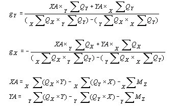
1. If the story shear force directions
are in the GCS X & Y directions
where,
: Sum of all
the vertical members at a corresponding story for each X-dir. seismic
load and Y-dir. seismic load
: X, Y coordinates
of the center (GCS)
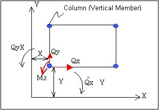
: X-dir.
horizontal component of vertical members
: Y-dir. horizontal component of vertical members
: Moment about Z-dir. of vertical members
X, Y: X, Y coordinates of vertical member
(column head coordinates for inclined columns)
2. If the story shear force directions
are not in the GCS X & Y directions
Since one load case (either
earthquake in X-dir. or earthquake in Y-dir.) can not determine the location
of the center, the intersection of the centers of story shear forces for
both load cases (X & Y-dir. earthquakes) is calculated.
Story Stiffness Center
Select load cases, which will be applied
to calculate the story stiffness center for calculating eccentricity ratios.
Each of
these load cases is assumed to be parallel with GCS X, Y axes. The
stiffness is also calculated on the basis of load cases, which are not
parallel with X, Y axes in which cases a warning message is generated.
X-Directional
Load: Select a load case, which will be used to calculate the story
stiffness center relative to Y-axis.
Y-Directional
Load: Select a load case, which will be used to calculate the story
stiffness center relative to X-axis.
Produce the Story Displ/Vel/Accel results
for Story Center using the method selected from Story Center(Mass/Load).
Story Average
Calculate the Story Displ/Vel/Accel results
averaging the story results of each vertical member. This option can be
used when Story Center is not calculated (Eccentricity Ratio option is
not used) or when Story Diaphragm is not assigned.

 Use Ground Level
 New for Gen2010

 : X,
Y coordinates of the center (GCS)
: X,
Y coordinates of the center (GCS) , : Column head moments (GCS
X, Y components)
, : Column head moments (GCS
X, Y components)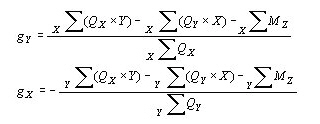
 : Sum of all
the vertical members at a corresponding story for each X-dir. seismic
load and Y-dir. seismic load
: Sum of all
the vertical members at a corresponding story for each X-dir. seismic
load and Y-dir. seismic load : X, Y coordinates
of the center (GCS)
: X, Y coordinates
of the center (GCS) : X-dir.
horizontal component of vertical members
: X-dir.
horizontal component of vertical members : Y-dir. horizontal component of vertical members
 : Moment about Z-dir. of vertical members