A single Haunched Beam can be assigned
when the Haunched Beam consists of a number of line elements (beam elements).
From the Main Menu
select Design > General
Design Parameter > Haunched Beam Assignment.
From the Menu tab
of the Tree Menu
select Design > General
Design Parameter > Haunched Beam Assignment.
Select the corresponding elements, and enter
the following.
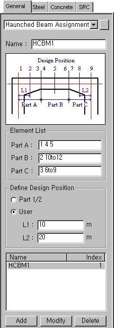
Name
Enter
the Name to be assigned as a haunched beam.
Element List
Part A:
Enter the element numbers corresponding to the end part (haunch part).
Part B:
Enter the element numbers corresponding to the center part (uniform part).
Part C:
Enter the element numbers corresponding to the end part (haunch part).
Define Design Position
Part 1/2:
Check strength at 1/2 point of Part
User:
Specify the position to check strength
L1:
Distance from the i-end to point 2
L2:
Distance from the j-end to point 8
Note 1
This option specifies the
design positions for end parts (haunch parts). L1 cannot exceed the length
of Part A and L2 cannot exceed the length of Part C. For Part A and C,
the automatic design results are based on the positions (I, 1/2, J) of
Tapered section. For Part B, the automatic design results are based on
the segments (I, M, J). The position M represents one of 1/4, 1/2 &
3/4 positions of Part B considered for the results of the automatic design,
based on most unfavorable negative and positive moments and shear forces.
Note 2
When a number of elements
are assigned as a single Haunched Beam, the Haunched Beam number retains
the smallest element number. That element then becomes the representative
element. All design parameters for the Haunched Beam must be input in
the representative element.
: Assign selected elements
as a haunched beam member.
 Name
Name : Assign selected elements
as a haunched beam member.
: Assign selected elements
as a haunched beam member. : Modify the selected haunched
beam member.
: Modify the selected haunched
beam member. : Delete the selected haunched
beam member
: Delete the selected haunched
beam member