Modify Beam Rebar Data | ||
|
| ||
|
| ||
|
Enter the rebar data and the concrete cover thickness for RC beam members for strength verification. | ||
|
| ||
|
| ||
|
| ||
|
From the Main Menu select Design > Concrete Design Parameter > Modify Beam Rebar Data.
From the Menu tab of the Tree Menu select Design > Concrete Design Parameter > Modify Beam Rebar Data. | ||
|
| ||
|
| ||
|
Main Rebar
Top: Enter the data of top rebar.
1: Enter the number and size of top Rebar in Layer 1.
2: Enter the number and size of top Rebar in Layer 2.
Bottom: Enter the data of bottom rebar.
1: Enter the number and size of the bottom rebar in Layer 1.
2: Enter the number and size of the bottom rebar in Layer 2.
Stirrup : Enter the rebar size, the number of legs and the spacing of stirrup bars
Note. When IS456:200 design code is selected
1. Under the IS456:2000 Concrete Design Code, only an even number of legs can be selected.
2. Limitations: a. When a user assigned an odd number and changed the design code to IS456:2000, the design won’t be performed for the corresponding members. b. When a user opens the Design Criteria for Rebar dialog after assigning an odd number with IS456:2000 design code, the value will changed to '2' automatically.
Skin : Enter the rebar size and the spacing of side bars
Note. This row can be activated for torsional strength verification as per Taiwanese design code (TWN-USD92).
dT : Distance between the center of the top main rebars in the upper layer and the top surface of the section (cover thickness)
dB : Distance between the center of the bottom main rebars in the lower layer and the bottom surface of the section (cover thickness)
Note
Same Main Rebar Size at Top and Bottom: Check on when the top rebar size is identically placed to the bottom rebar size.
Same Main Rebar Size at I, M and J: Check on when the rebar size of i-end, middle and j-end are identically placed.
| ||
|
|
 Revision of Gen2010
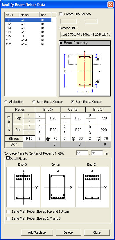
 Section
List
Section
List