Enter the design criteria for shear wall members- the standard rebar
sizes, the rebar placement, the number of rebars, the thickness of the
shear wall section, etc., for the stories assigned by the user for strength
verification.
From the Main
Menu select Design
> Concrete Design Parameter > Modify Wall Section Data.
From the Menu
tab of
the
Tree Menu select Design
> Concrete Design Parameter > Modify Wall Section Data.
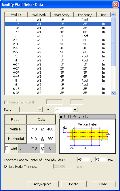
Wall ID List
Select the wall IDs for which their rebar
data will be changed.
Wall ID:Shear wall ID number
Wall
Mark: Wall mark names
Start
Story: The first story from which the rebar data are applicable
End
Story: The last story to which the rebar data are applicable
Bar:
Status of rebar placement
(In:
rebars are placed, -: rebars are not placed)
Create
Sub Section
Add or modify rebar data of a Sub-Section.
(ex. Wall ID-1F, 2F,3F...)
Note 1
Sub-section is useful when the user needs
to place a different rebar data to members which are defined as the same
wall ID.
Note 2
If the user deletes a rebar data of Sub-Section,
the member will be changed to their initial rebar data. For example, if
'411-1' sub-section rebar data is deleted, the rebar data of the corresponding
members is changed to' 411' rebar data.
Story
Select the first story and the last story
for which the rebar data are applicable
Note
Enter the range of stories of shear wall members for which strength verification
is to be performed. The Start Story must be entered prior to entering
the End Story. The End Story number
may be equal to or greater than the Start Story number.
Rebar Data
Enter the rebar data for strength verification.
Vertical:
Enter the standard rebar size and spacing of the vertical rebars in the
shear wall member.
Note
The reinforcing placement for vertical rebars
in shear wall members must be in two layers.
Horizontal:
Enter the standard rebar size and spacing of the horizontal rebars in
the shear wall member.
End:
Determine whether to use end rebars. If selected, the number of the end
rebars, the rebar size and spacing
must be entered.
Note
The end rebar data apply to both ends of the shear wall members. It is
assumed that the end rebars are symmetrically placed with respect to the
member's strong axis.
Concrete Face to Center of Rebar
Enter the distance (cover thickness) between
the center of the rebars and the surface of the shear wall.
dw:
Distance from the center of the end vertical rebars to the end of the
shear wall
de:
Distance from the end of the shear wall member to the center of the first
row of the vertical rebars
Note
This provides the design data for cover dimensions. When
the cover is not specified or 0 is entered, default
value specified by the design code are applied.
Wall
Thickness
Enter the thickness of the shear wall member
for strength verification.
Use Model
Thickness: Use the wall thickness entered during the creation of
the analysis model.
Thickness:
Thickness of the shear wall member
When Use Model Thickness is selected, the
thickness cannot be entered.
Operation
Add/Replace:
Add the newly entered values or update the previously entered values.
Delete:
Delete the entered values. Data entry is not required when deleting.
 Wall ID List