Data Conversion
| ||||||||||||||||||||||||||||||||||||||||||||||||||||||||||||||||||||||||||||||||||||||||||||||||||||||||||||||||||||||||||||||||||||||||||||||||||||||||||||
|
| ||||||||||||||||||||||||||||||||||||||||||||||||||||||||||||||||||||||||||||||||||||||||||||||||||||||||||||||||||||||||||||||||||||||||||||||||||||||||||||
|
| ||||||||||||||||||||||||||||||||||||||||||||||||||||||||||||||||||||||||||||||||||||||||||||||||||||||||||||||||||||||||||||||||||||||||||||||||||||||||||||
|
Convert model data and analysis results of MIDAS/Gen into model data or loads for MIDAS/SDS, or vice versa. MIDAS/SDS is a specialized program for floor/mat plate analysis.
Structural Frame Systems, Floor Systems and Foundation Systems are generally separated for structural analysis and design.
In such cases, analysis data for both systems must be prepared separately. Data Conversion allows the user to avoid such duplication and transfer the geometry and load data back and forth between the frame and floor/mat design analyses. The Data Conversion feature is especially useful for residential reinforced concrete structures with flat plates and irregular shear/bearing walls.
Data Conversion of MIDAS/Gen performs the following functions:
1. The coordinates of the floor framing from the MIDAS/Gen framing model data are extracted. MIDAS/Gen data are converted into MIDAS/SDS model data (MIDAS/Gen-> MIDAS/SDS, Model Data). Equivalent stiffness of beams, columns, diagonals and walls of the frame model connected to the floor plate are automatically calculated and entered as elastic support conditions in the floor plate analysis model. For the analysis of a foundation mat, wall elements are converted into beam elements of equivalent stiffness. The stiffness of elastic supports is not generated automatically
2. The MIDAS/SDS reaction data resulting from the floor plate analysis are automatically entered as load data in the MIDAS/Gen frame model (MIDAS/SDS->MIDAS/Gen, Load Data).
3. The support reactions resulting from the MIDAS/Gen analysis are automatically converted into MIDAS/SDS model load data for foundation mat analysis. (MIDAS/Gen->MIDAS/SDS, Reaction Data)
To use Data Conversion, story data must be previously entered to assign the floor plate subjected to conversion.
The elements in a frame model to be converted into a floor plate model may be beam elements on the same plane, beam or truss elements (columns or diagonals) connected to the plane and wall elements. The floor plate elements and the analysis data must be additionally entered in MIDAS/SDS using the Object.
The following data are created during a conversion process, from a MIDAS/Gen frame model into a MIDAS/SDS floor plate analysis model:
Note
1. For wall elements, a beam element with an equivalent wall stiffness is additionally created to connect the ends of a wall element. The beam element is required to maintain the connectivity between vertical line springs, which constitute a line elastic support.
2. Refer to MIDAS/SDS On-line Manual for the features of MIDAS/SDS.
When the MIDAS/SDS analysis is completed, the nodal load data of MIDAS/Gen are created using Data Conversion once again.
The method of converting the reaction data of the MIDAS/SDS floor plate analysis model into nodal load data of MIDAS/Gen is as follows:
The reactions at the point-elastic supports representing column or diagonal members are converted into nodal loads (vertical concentrated loads or moments) of MIDAS/Gen.
The reactions at the line spring supports representing wall elements are transformed into two point reactions at both ends of walls as if the walls were simply supported beams.
The MIDAS/Gen reaction data at the supports are converted into MIDAS/SDS concentrated load data as below.
| ||||||||||||||||||||||||||||||||||||||||||||||||||||||||||||||||||||||||||||||||||||||||||||||||||||||||||||||||||||||||||||||||||||||||||||||||||||||||||||
|
| ||||||||||||||||||||||||||||||||||||||||||||||||||||||||||||||||||||||||||||||||||||||||||||||||||||||||||||||||||||||||||||||||||||||||||||||||||||||||||||
|
| ||||||||||||||||||||||||||||||||||||||||||||||||||||||||||||||||||||||||||||||||||||||||||||||||||||||||||||||||||||||||||||||||||||||||||||||||||||||||||||
|
| ||||||||||||||||||||||||||||||||||||||||||||||||||||||||||||||||||||||||||||||||||||||||||||||||||||||||||||||||||||||||||||||||||||||||||||||||||||||||||||
|
From the Main Menu select File > Data Conversion > MIDAS/Gen –> MIDAS/SDS (Model + Reaction Data). From the Main Menu select File > Data Conversion > MIDAS/SDS –> MIDAS/Gen(Load Data). | ||||||||||||||||||||||||||||||||||||||||||||||||||||||||||||||||||||||||||||||||||||||||||||||||||||||||||||||||||||||||||||||||||||||||||||||||||||||||||||
|
| ||||||||||||||||||||||||||||||||||||||||||||||||||||||||||||||||||||||||||||||||||||||||||||||||||||||||||||||||||||||||||||||||||||||||||||||||||||||||||||
|
| ||||||||||||||||||||||||||||||||||||||||||||||||||||||||||||||||||||||||||||||||||||||||||||||||||||||||||||||||||||||||||||||||||||||||||||||||||||||||||||
|
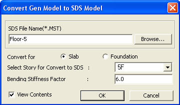
Convert a MIDAS/Gen model into a MIDAS/SDS model data for a floor. The conversion serves to create a MIDAS/SDS floor plate or foundation mat analysis model in the structural analysis of a residential building with irregular shear wall layout.
Convert MIDAS/Gen Model to MIDAS/SDS Model dialog box
|


 Modulus of elasticity
 Cross sectional area
 Floor height
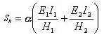
 Modulus of elasticity
of the upper and lower members
Modulus of elasticity
of the upper and lower members Moments of inertia of the upper and lower members
 Upper and lower level
heights
Upper and lower level
heights|
- |
Roof |
Roof floor-1 |
Roof floor-2 |
Roof floor-3 |
Roof floor-4 |
Roof floor-5 |
Roof floor-6 |
Roof floor-7 |
Roof floor-8 |
Roof floor-9 |
Roof floor-10 |
|
1-story structure |
4.0 |
- |
- |
- |
- |
- |
- |
- |
- |
- |
- |
|
2-story structure |
4.7 |
7.0 |
- |
- |
- |
- |
- |
- |
- |
- |
- |
|
3-story structure |
4.3 |
13.0 |
4.4 |
- |
- |
- |
- |
- |
- |
- |
- |
|
4-story structure |
4.4 |
10.8 |
5.7 |
4.9 |
- |
- |
- |
- |
- |
- |
- |
|
5-story structure |
4.4 |
11.3 |
5.3 |
6.7 |
4.7 |
- |
- |
- |
- |
- |
- |
|
6-story structure |
4.4 |
11.2 |
5.4 |
6.1 |
6.4 |
4.8 |
- |
- |
- |
- |
- |
|
7-story structure |
4.4 |
11.2 |
5.4 |
6.3 |
5.9 |
6.5 |
4.8 |
- |
- |
- |
- |
|
8-story structure |
4.4 |
11.2 |
5.4 |
6.2 |
6.0 |
5.9 |
6.5 |
4.8 |
- |
- |
- |
|
9-story structure |
4.4 |
11.2 |
5.4 |
6.2 |
6.0 |
6.1 |
5.9 |
6.5 |
4.8 |
- |
- |
|
10-story structure |
4.4 |
11.2 |
5.4 |
6.2 |
6.0 |
6.0 |
6.0 |
5.9 |
6.5 |
4.8 |
- |
|
More than 10 stories |
4.4 |
11.2 |
5.4 |
6.2 |
6.0 |
6.0 |
... |
6.0 |
5.9 |
6.5 |
4.8 |
|
- |
Roof |
Roof floor -1 |
Roof floor -2 |
Roof floor -3 |
Roof floor -4 |
Roof floor -5 |
... |
5th story floor |
4th story floor |
3rd story floor |
2nd story floor |
<Table> Bending stiffness factor,  , for column, diagonal and wall elements
*For structures higher than 10 stories, use the values specified in the table for the portions between 2nd and 4th stories and between (roof -4) and roof floors. Use 6.0 for the portion between 5th and (roof -5).
* Assumptions
the heights of all the stories are identical
the cross sectional areas of columns (or walls) of all the stories are
identical
the thickness of floor plates and column capitals
are neglected
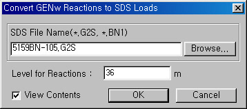
Convert MIDAS/Gen Reactions to MIDAS/SDS Loads dialog box
Note
If Convert for Foundation is selected, the reactions
resulting from the structural analysis of a MIDAS/Gen frame model are
converted into load data of a MIDAS/SDS model. The reactions for each
load case of the MIDAS/Gen model are automatically entered as point loads
including the results of response spectrum analysis. As a result, the
signs deleted during the process of load combinations for modal analysis
must be reproduced.
(Refer to "Response Spectrum Analysis Control")
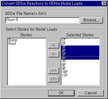
Convert MIDAS/SDS Reactions to MIDAS/Gen Nodal Loads
The reactions resulting from MIDAS/SDS floor plate analysis are converted into load data for MIDAS/Gen frame structural model.
 MIDAS/SDS File Name(*.SA1, *.BN2)
Enter the name of the MIDAS/SDS floor plate analysis model to be converted into load data.
Select Stories for Nodal Loads
Convert the reactions of the floor plate analysis model into load data for MIDAS/Gen frame structural model. Select the floors onto which the reaction data are to be loaded. Multiple selection is feasible.