Display specific symbols or numerical values for various attributes
to check the data entry status on the screen. The information can be node
and element numbers, material properties, section types, boundary conditions,
loads, etc.
From the Main
Menu select View
> Display.
Click Display in the Icon
Menu.
Shortcut key:
[Ctrl]+E
The types of specific symbols and numerical values that can be represented
are as follows:
Node tab
Node
Node Number
Story Name
Node Local
Axis: Coordinate axes displayed at the nodes assigned with nodal
local coordinate systems.
Display
dialog box
Element tab
Element Number
Element Type Number
Element Type Name
Wall Type
Wall ID:
Wall combination numbers
Gap:
Gap Element shape
Hook:
Hook Element shape
Cable:
Cable Element shape
Local Axis:
Element's local coordinate axes
Local Direction:
Nodal connection directions of elements (i >> j node, N1 > N2
> N3 > N4)
Property tab
Material Number
Material Name
Property
Number: Section or thickness numbers
Property
Name: Section or thickness names
Section
Shape: Sectional shapes of line elements
Tapered
Section Group: Elements assigned to the Tapered (variable) Section
Group
Revision
of V.7.6.1
Boundary tab
All:
Display the boundary conditions include in all the boundary groups.
Group Selection:
Display the boundary conditions included in the selected boundary group.
Prompt
Select Boundary Group dialog box to select Boundary Group.
Support:
Display the constrained nodal degrees-of-freedom ()
Support
by Direction: Display the constrained nodal degrees-of-freedom
with a Digit (0: released, 1: constrained) ()
Point
Spring Support: Display Point Spring Support ()
Point
Spring Support (Comp/Tens) : Display Comp.-only/Tens.-only type
Point Spring Support
Point
Spring Support (Multi-Linear) : Display Multi-Linear type Point
Spring Support
Point
Spring Support by Direction : Display Linear, Comp.-only, Tens.-only
and Multi-Linear type of point spring support with a Digit (0: released,
1: constrained) ()
General Spring Support
Beam End Release
Symbol:
Symbol of beam end release condition
Digit:
Beam end release condition by degree-of-freedom with a Digit (0: connected,
1: released)
Beam End Offset
Plate End Release
Symbol:
Symbol of beam end release condition
Digit:
Beam end release condition by degree-of-freedom with a Digit (0: connected,
1: released)
Rigid Link:
Master node/slave nodes
Elastic
Link: Elastic link between two nodes
Local Axis:
Element's local coordinate axes of elastic link elements
Story Diaphragm:
Display entry status of Story Diaphragm
Diaphragm
Disconnect: Display the state of Floor Rigid Diaphragm release.
Misc tab
Mass
Nodal Mass:
State of Nodal Mass data entry
Load to
Mass: Gravity load converted into mass
Floor Diaphragm
Mass: State of Floor Diaphragm Mass data entry
Story Mass,
Stiffness: Display Story Mass Center and Stiffness Center.
Note
It can be checked in the post-processing mode when Story Center for Eccentricity
Ratio is selected in Model > Building > Control Data.
Moving Load
Line Lane:
Traffic (line) lane
Surface
Lane: Traffic (surface) lane
Influence
Surface: Elements inclined in Influence Surface analysis
Lane Support:
Continuous span supports
Dynamic
Nodal load: Dynamic Nodal Loads for time history analysis
Initial
Forces for Geometric Stiffness: State of Initial Axial Forces data
entry for Geometric Stiffness
Push Over
Hinges: Display the hinges formed in the process of Pushover Analysis
Symbol:
Display the symbol representing hinges
Type:
Display the defined types of hinges
Name:
Display the hinges by names
Hydration
Heat: State of data entry for Heat of Hydration
Value:
Numerical data
Func Name:
Function Name of data related to Heat of Hydration
Element Convection Boundary
Prescribed Temperature
Heat Source
Pipe Cooling Elements
Settlement
Group:Settlement Group
for a bridge structure
Value:
Magnitude of settlement
Erection Sequence
Model:
Erection Sequence for the structure
Load:
Loads pertaining to Erection Sequence
From ~
To ~: Select of multiple Erection Sequence
Tendon Profile:
Display the Tendon Profile
Name:
Tendon name
Point:
Reference point for defining the tendon profile
Load tab
Load Case
Select the load case for which the load input status will be displayed
and assign whether to display the load values.
All:
Select all the load cases
Load Value:
Option to display the load values
Note
1
If Floor Load Name is checked the load values defined for Floor Load Type
are also displayed.
Case Selection:
Select a desired load case
Group Selection:
Select the desired Load Group
: Prompt Select Load Group
dialog box to select Load Group
The following data related to loads, masses
and moving loads may be displayed:
Nodal Load:
Nodal concentrated loads
Specified
Displacement: Forced displacements
Beam Load
Prestress Load
Pretension Load
Floor Load:
Display floor plate loads converted into beam loads
Floor Load Name
Note
1
When Floor Load Name and Load Value are checked, the Load Values for each
load cases defined in Floor Load Type are displayed.
If Load Type Color as assigned to Floor Load Color under the Draw Tab of
Display Option, colors can be assigned to each Floor Load Type thereby
allowing us to check the Floor Loads readily.
Note
2
From the Floor Load Name in Display, load distribution Type can be checked.
ex) One Way =(One), Two
Way =(Two), Polygon - Centroid =(P-C), Polygon-Length = (P-L)
Note
3
The display of Floor Load Name is located at the center of the Floor Load
application area. If
the center deviates from the application (loaded) area, Floor Load Name
is displayed on the line connecting the 1st point and 2nd point.
Note
4
Display an arrow in the direction of floor load (One Way) at the center.
Load direction is displayed following the Load Angle(A1) entered in Assign Floor
Loads.
Pressure Load
Plane Load:
Display plane loads applied to a plane
Plane Load
Name: Display the plane loads
Nodal Temperature
Element Temperature
Temperature Gradient
Beam Section Temperature
Tendon Prestress
Wind Load
Seismic
Load: Statically equivalent seismic loads
Dynamic
Nodal Load: Dynamic Nodal Loads for time history analysis
View tab
UCS Axis:
Display UCS or GCS axes at the origin
View Point:
Display GCS axes at the lower-right corner of the screen
Description
Description is displayed at the top-left
position of the current Model Window. The size of the lower entry window
dose not affect the size of entry.
Font:
Assign the font, size and type of the description.
Note
The description displayed on the Model Window can be dragged and moved.
Label Orientation:
Design tab
Member:
Display the assigned members.
Note
Display color gradient of the element when Hidden option is selected in
the preprocessing mode.
Member Direction:
Display the direction of the nodal connection of members.
Note
Display color gradient of the element when Hidden option is selected in
the preprocessing mode, and display the direction of the arrow so as to
represent elements as Wire Frame in the post-processing mode.
Member Number:
Display the index of the assigned member.
Unbraced
Length Ly: Display the unbraced length about the strong axis of
the selected member.
Unbraced
Length Lz: Display the unbraced length about the weak axis of the
selected member.
Lb:
Laterally braced length
Effective
Length Factor Ky: Display the effective buckling length factor
about user-defined strong axis.
Effective
Length Factor Kz: Display the effective buckling length factor
about user-defined weak axis.
Effective
Length Factor Ky Contour: Display the effective buckling length
factor about auto-defined strong axis.
Effective
Length Factor Kz Contour: Display the effective buckling length
factor about auto-defined weak axis.
Moment Factor
Cmy: Display equivalent moment factor for bending about the member’s
strong axis within the unbraced length.
Moment Factor
Cmz: Display equivalent moment factor for bending about the member’s
weak axis within the unbraced length.
Moment Magnifier
B1y | Delta-by: Moment magnification factor for members subjected
to vertical loads in a frame braced against sidesway for strong axis bending
Moment Magnifier
B1y | Delta-bz: Moment magnification factor for members subjected
to vertical loads in a frame braced against sidesway for weak axis bending
Moment Magnifier
B2y | Delta-sy: Moment magnification factor for members subjected
to horizontal loads in a frame unbraced against sidesway for strong axis
bending
Moment Magnifier
B2z | Delta-sy: Moment magnification factor for members subjected
to horizontal loads in a frame unbraced against sidesway for weak axis
bending
Member Type:
Display the type of members.
Wall Mark
Member Type
Bending Coefficient (Cb)
Shear Coefficient (Cv)
Display by
Group
Display specific symbols or values for selected
group in the screen.
Display by Selection
Display specific symbols or values for selected
elements or nodes on the screen.
Display by Member
Display specific symbols or values of the
items assigned from each tab for only the selected members on the screen.
 Display
 Node tab
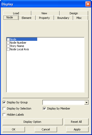

 Prompt
Select Boundary Group dialog box to select Boundary Group.
Prompt
Select Boundary Group dialog box to select Boundary Group. )
) )
) )
) )
) : Open the
 : Initialize the entry status
by deleting all labels except for the node label.
: Initialize the entry status
by deleting all labels except for the node label.