Use Frame Wizard to auto-generate a 2-D plane grid frame composed of
Beam Elements in 3-D.
From the Main
Menu select Model > Structure Wizard > Frame.
Select Geometry
> Structure Wizard > Frame from the Menu tab of the Tree Menu.
Shortcut key:
[Ctrl]+[Shift]+X
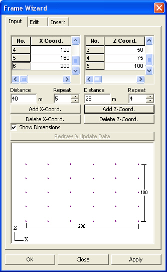
Input
dialog box
Input tab
Distance
Enter the distance between the nodes.
Repeat
Enter the number of repetitions to create multiple beam elements in a grid
pattern.
,
Create nodes as per the entered distances between nodes and the number
of repetitions.
,
Delete a grid in the corresponding coordinate direction.
Show Dimensions
Display the dimensions entered in the Wizard Window.
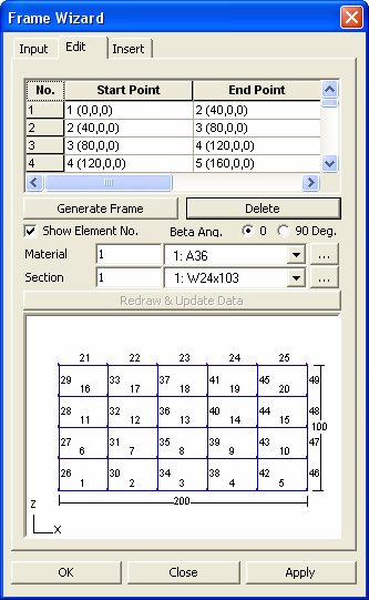
Edit dialog box
Edit tab
Use the entered nodes to generate the basic elements.
Delete the selected elements. After eliminating the elements, the elements
are automatically renumbered.
Show Element
No.
Display the element numbers of the generated plane frame.
Beta Ang.
Select the Beta Angles for the generated elements.
to add a new material property or modify
an existing material property.
Material
Enter the material property to be used.
Click to add a new material
property or modify an existing material property.
Section
Enter the section to be used.
Click to add a new section
or modify an existing section.
Insert dialog box
Insert tab
Insert
Point
Enter the coordinates of the insert point
where the origin point of the generated grid frame will be located in
the existing model with respect to the GCS(UCS).
Alternatively, click the entry field and
click the position of the insert point in the working window to enter
the desired coordinates rather than typing in the entry field.
Rotations
Enter the rotational angles, Alpha, Beta and Gamma, that will define the
orientation of the frame in GCS X, Y and Z respectively.
Merge Duplicate
Nodes
Select the option whether to merge overlapping nodes between the existing
model and the nodes pertaining to the newly created grid frame.
: Set a tolerance for
merging nodes.
Intersect
Frame Elements
Select the option whether to divide the existing elements at the nodes
pertaining to the newly created frame, which are in contact with the existing
elements in the existing model.
: Set an intersecting
tolerance to allow for the division of elements.
Origin Point
Set the origin point of the newly created frame. This point is displayed
in red in the Wizard Window.
Show No.:
Display the node numbers making up the created frame.
 Input tab
 ,
,
 ,
,


 to add a new material
property or modify an existing material property.
to add a new material
property or modify an existing material property.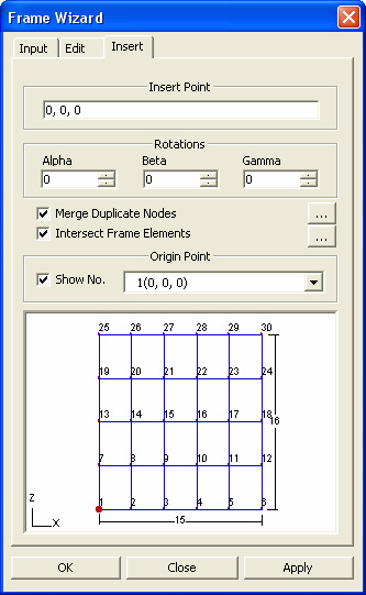
 Insert
Point
Insert
Point