Project Nodes
| ||||||||||||||||||
|
| ||||||||||||||||||
|
| ||||||||||||||||||
|
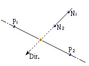
Move or copy nodes by projection on a particular line or surface. | ||||||||||||||||||
|
| ||||||||||||||||||
|
| ||||||||||||||||||
|
| ||||||||||||||||||
|
From the Main Menu select Model > Nodes > Project.
Select Geometry > Nodes > Project in the Menu tab of the Tree Menu.
Click
Shortcut key: [Ctrl]+[Alt]+5 | ||||||||||||||||||
|
| ||||||||||||||||||
|
| ||||||||||||||||||
|
 Project Nodes
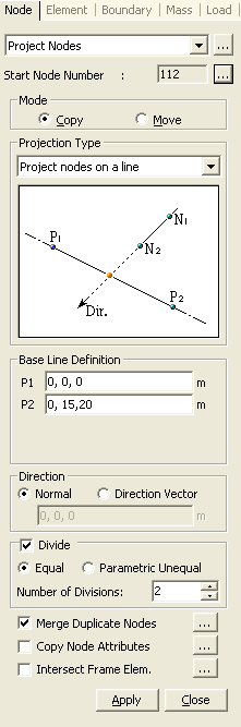
|
|
|
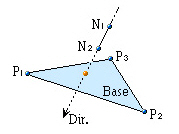
Project nodes on a plane
|
|
|
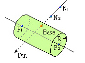
Project nodes on a cylinder
|
|
|
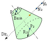
Project nodes on a cone
|
|
|
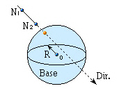
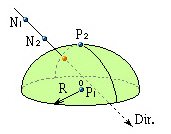
Project nodes on a sphere
|
|
|
Project nodes on an ellipsoid
|
|
|
Project nodes on an ellipsoid
|
|
|
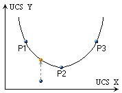
Project nodes on an element
|
|
|
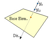
 Direction
Assign the projection direction for the line or surface of the defined projection base.
Normal: Projection direction normal to the line or surface of the projection base
 Direction Vector: Projection in an arbitrary direction.
Enter each of the x, y, z vector components in the projection direction.
Direction Vector: Projection in an arbitrary direction.
Enter each of the x, y, z vector components in the projection direction.
Divide
Create additional elements in between the existing nodes and projected nodes along the lines of projection at either equal or unequal spacings.
Equal: Equal spacing
Number of Divisions: Number of equal spacings
Parametric Unequal: Unequal spacings defined in terms of distance ratios.
Ratio: Locations of division along the total projection length expressed in terms of distance ratios. (ex: 0.4, 0.6, 0.9)
Merge Duplicate Nodes
Merge overlapping nodes to single nodes if
new nodes coincide with existing nodes. Click  to modify
the Merging Tolerance.
to modify
the Merging Tolerance.
Copy Node Attributes
Select the option whether to copy the attributes
(nodal boundary conditions, nodal concentrated loads, etc.) to the nodes
being copied. Click to assign desired attributes selectively.
Intersect Frame Elem
If line elements exist at the locations to
which nodes are project-copied or moved, divide the line elements at the
corresponding nodes. Click to control the tolerance for
the intersecting condition of a node and a line element.