Change Element Parameters
| ||||||||||||||||||||||
|
| ||||||||||||||||||||||
|
| ||||||||||||||||||||||
|
Change the attributes of entered elements (Material property number, Section number, Thickness number, Beta Angle, etc.). | ||||||||||||||||||||||
|
| ||||||||||||||||||||||
|
| ||||||||||||||||||||||
|
| ||||||||||||||||||||||
|
From the Main Menu select Model > Elements > Change Element Parameters.
Select Geometry > Elements > Change Element Parameters in the Menu tab of the Tree Menu.
Click
Shortcut key: [Alt]+9 | ||||||||||||||||||||||
|
| ||||||||||||||||||||||
|
| ||||||||||||||||||||||
|
Click
| ||||||||||||||||||||||
 Change Element Parameters
 to the right of
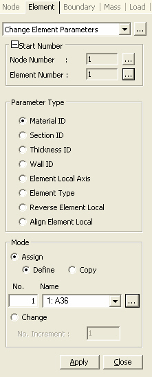
|
|
|
|
|
Assign: Reassign relevant attribute.
Define: Define a material property for change of element properties.
Copy: If Material Property, Section or Thickness is to be changed, copy the property assigned to the selected elements and change them to the auto-generated property numbers.
Copy per Property: Copy properties by Property numbers.
Copy per Element: Copy properties by Element numbers.
Note the selected elements.
Change: the selected attribute by applying an increment. |
|
|
|
|
|
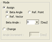
Assign: Reassign relevant attribute.
Beta Angle: Enter Beta Angle directly.
Ref.Point: Select a node in the positive z-direction on the element’s local x-z plane.
Ref.Vector: Select a vector, which will define a plane in which ECS z-axis lies (x-z or y-z plane).
Change: Redefine the selected attribute by applying an increment. |
|
|
|
|
|
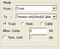
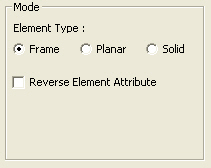
From: Display the element type of the selected elements.
To: Select an element type to which the old type will be changed.
Changes pertain to the same element types, i.e., a line type to a line type and a planar type to a planar type.
For more information related to required element properties, please refer to Create Elements. |
|
|
|
|
|
Reverse Element Attribute: When element local coordinate systems are to be reversed, reverse the element boundary conditions, static loads, etc., as well. |
|
|
|
|
|
Align Order: Where selected elements are aligned to correspond to the reference element's local coordinate system, enter the order of priority for the element local coordinate axes.
Note In the case where complete correspondence cannot be established for the element local coordinate axes, change the coordinate system as close to the 1st Order coordinate axis as possible.
|
 When Material ID/ Section
ID/ Thickness ID is selected
When Material ID/ Section
ID/ Thickness ID is selected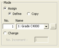
 Parameter Type
Assign: Reassign relevant attributes.
Define: Define the property if the elements to be changed.
Copy: If Material Property, Section or Thickness is to be changed, copy the property assigned to the selected elements and change them to the auto-generated property numbers.
Copy per Property: Copy properties by Property numbers.
Copy per Element: Copy properties by Element numbers.
Note
If Copy per Property is assigned, new properties are created as many as
the number of property types of the selected elements.
If Copy per Element is assigned, new properties are created as many as
the selected elements.
Change: Reassign relevant attributes with a defined increment.
Reverse Element Attribute
When element local coordinate systems are to be reversed, reverse the element boundary conditions, static loads, etc., as well.
 Standard
Element
Standard
Element
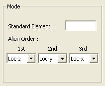
When Align Element Local is selected the reference element number is specified.
Align Order
Where selected elements are aligned to correspond to the reference element's
local coordinate system, enter the order of priority for the element local
coordinate axes.
Note
In the case where complete correspondence cannot be established for the
element local coordinate axes, change the coordinate system as close to
the 1st Order coordinate axis as possible.