Define a curve on a particular plane and create line elements on the
curve.
From the Main
Menu select Model > Elements > Create Line Elements on Curve.
Select Geometry
> Elements > Create Line Elements on Curve from the
Menu tab of
the Tree Menu.
Click Create Elementson
Curve in the
Icon Menu.
Click to the right of Create Line
Elements on Curve : Display the Element Table.
Start Node Number
Assign a number to the new starting node
created together with new elements in the Model Window. This number is
auto-set to the largest node number in use +1. To modify this item, click
and select an option to specify a desired number.
Start Element Number
Assign a new starting element number. This
number is auto-set to the largest element number in use +1. To modify
this item, click and select an option to specify a desired
number.
Curve Type
Select the shape of a curve onto which line
elements will be created and the method of defining the curve.
Arc by
3 points
Define an arc by assigning 3 particular points
Arc by
Center and 2 points
Define an arc by assigning 2 particular points and the center of the arc
Circle
by 3 points
Define a circle by assigning 3 particular points
Circle
by Center and 2 points
Define a circle by assigning 2 particular points and the center of the
circle
Ellipse
by Center and 2 points
Define an ellipse by assigning 2 particular points and the center of the
ellipse
Parabolic
Curve by 3 points
Define a parabolic curve by assigning 3 particular points
Cubic Curve
by 4 points
Define a cubic curve by assigning 4 particular points
Element Type
Assign the type of line elements to be created
along the curve
Material / Section / Orientation
Material
Select a material property number, or select a material property name provided
that the material property data have been already defined.
No.:
Type in a number on the keyboard or use the mouse to enter the number
Name:
Select a material property name
Click to add, inquire, modify
or delete material property data. Material properties can be entered either
before or after creating elements.
Section
Select a section number, or select a section name provided that the section
data have been already defined.
No.:
Type in a number on the keyboard or use the mouse to enter the number
Name:
Select a section name
Click to add, inquire, modify
or delete the section data. Section data can be entered either before
or after creating elements.
Orientation
Beta Angle:
Enter a Beta Angle to assign the sectional orientation of the line elements.
Curve Definition
Define a curve on which new line elements
will be created.
Number
of Segments: Number of segments in the curve to define new elements
The data entry items for each method of defining
the curves are as follows :
Arc by
3 points
Arc End
Point: Assign the method of defining the end of the arc
P3:
Create elements up to the 3rd point on the arc
Angle:
Enter the angle of the arc within which new elements will be created
P1: Enter the coordinates of the starting point of
the arc
P2, P3: Enter the coordinates of two points on the
arc
The arc is created in the direction determined
by the sequential direction of P1, P2 & P3.
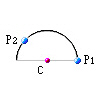
Arc by Center and 2 points
Arc End
Point: Assign the method of defining the end of the arc
P2:
Create line elements up to the fictitious line connecting P2 and the center
of the arc center
Angle:
Enter the angle of the arc within which new elements will be created
C: Enter the coordinates of the center of the arc
P1: Enter the coordinates of a particular point on
the arc
P2: Create line elements up to the fictitious line
connecting P2 and the arc center.
The arc is created in the direction along
the curve from P1 to P2 following the shorter distance. To create the
arc in the longer arc direction, Angle is used to control the direction.
Note
The arc cannot be created if P1, C and P2 are on a straight line. In such
a case, use Angle to create the arc.
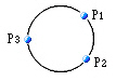
Circle by 3 points
P1: Enter the coordinates of the starting point of
a circle
P2, P3: Enter the coordinates of two points on the
circle
The circle is created in the direction determined
by the sequential direction of P1, P2 & P3.
Circle by Center and
2 points
C: Enter the coordinates of the center of a circle
P1: Enter the coordinates of the starting point of
the circle
P2: Assign a point on the plane of the circle
Ellipse by Center and
2 points
Semi-Ellipse:
To form a semi-ellipse
C: Enter the coordinates of the center of an ellipse
P1: Enter the coordinates of the starting point on
the axis of the longer dimension
P2: Enter the coordinates of a point on the ellipse
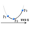
Parabolic Curve by 3
points
Divide by Equal distance
on
Curve:
Divide the curve into equal segments
Projecting
line: Divide the curve into equal segments along the length projected
on UCS (GCS) x-axis
P1: Enter the coordinates of the starting point of
a parabola
P2, P3: Enter the coordinates of two points on the
parabola
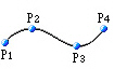
Cubic Curve by 4 points
P1: Enter the coordinates of the starting point of
a cubic curve
P2, P3, P4: Enter the coordinates of 3 points
on the cubic curve
Note
The Local Directions of the line elements are defined by the sequential
direction of P1, P2 & P3.
Intersect
Node:
when existing nodes are on the line elements being created, the elements
are divided at the existing nodes.
Element:
when newly created line elements intersect with existing line elements,
nodes are automatically created and the line elements are divided at the
intersection points.
 Create Elements
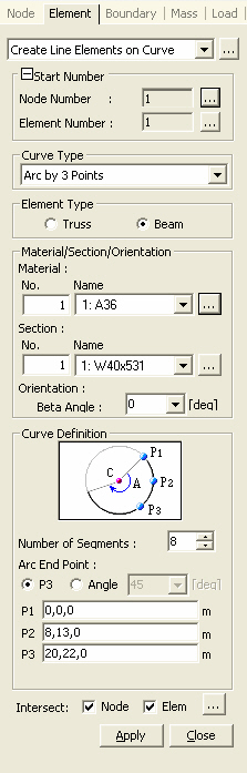
 to the right of
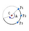
 P1
P1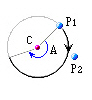

 Intersect