Create elements by extruding a node to a line element, a line element
to a planar element and planar element to a solid element.
Extrude Elements performs the following 3 functions.:
1. Create
line elements along the line path taken by the motion of nodes.
2. Create
planar elements along the surface path taken by the motion of line elements.
3. Create
solid elements along the volumetric path taken by the motion of planar
elements.
From the Main
Menu select Model > Elements > Extrude.
Select Geometry
> Elements > Extrude in the Menu tab of the Tree Menu.
Click Extrude Elements in the Icon Menu.
Shortcut key:
[Alt]+5
Click to the right of Extrude Elements: Display the Element
Table.
Start Node Number
Assign a starting number of the nodes automatically
created in the element generation process. This number is auto-set to
the largest node number in use +1. To modify this item, click and select an option to specify a desired number.
Start Element Number
Assign a new starting element number for
new elements being created by copy. This number is auto-set to the largest
element number in use +1. To modify this item, click and
select an option to specify a desired number.
Extrude Type
Select the conversion mode of nodes or elements
into the next higher level elements.
Node →
Line Element
Create line elements along the line path taken by the motion of nodes.
Line Elem.
→ Planar
Elem.
Create planar elements along the surface path taken by the motion of line
elements.
Planar
Elem. → Solid Elem.
Create solid elements along the volumetric path taken by the motion of
planar elements.
Source
Remove:
After executing Extrude, remove the original nodes/elements.
Move:
After executing Extrude, move the original nodes/elements to the final
positions of the extruded elements.
Reverse
I - J
If Node → Line Element is selected
in Extrude Type, the Local Direction of the line elements created by Extrude
is reversed to the Generation direction.
Element Attribute
Element
Type
Assign the type of newly created elements.
Line Element:
Truss, Beam, Tension, Compression... etc.
Planar
Element: Plate, Plane Stress, Plane Strain, Axisymmetric... etc.
Solid Element:
Solid
If Wall Element Type is selected, specify
whether it is a Membrane or Plate type and the Wall ID.
Material
Select a material property number, or select a material property name provided
that the material property data have been already defined. Click to add, inquire, modify or delete material property data.
Material properties can be entered either before or after creating elements.
Section
(or Thickness)
Select a section (thickness) number, or select a section (thickness) name
provided that the section (thickness) data have been already defined.
Click to add, inquire, modify or delete the section (thickness)
data. Section data can be entered either before or after creating elements.
Beta Angle
Specify beta angle for newly created line elements extruded from nodes.
Type
Assign a type of planar elements (thin/thick) for newly created elements
extruded from line elements.
Generation Type
Select the method of generating elements
via extrude.
Translate
Select Translate when creating elements by copying (translating) and extruding
existing nodes or elements at equal or unequal distances.
Equal Distance:
To translate at equal spacings
dx, dy, dz: Translation distance in each axis direction
To enter the translation distance, type
in each distance, or click the entry field and assign the translation
distance in the working window with the mouse.
Number of
Times: Number of times to copy
Unequal
Distance: To translate at unequal spacings
Axis:
Assign translation directions.
x:
Copy at unequal distances in UCS x-direction.
y:
Copy at unequal distances in UCS y-direction.
z:
Copy at unequal distances in UCS z-direction.
Arbitrary:
To copy at unequal distances in a specified direction
Distances:
Enter unequal copy distances in the specified direction as many times
as desired.
Specify distances in radial and rotational
axis directions when copying elements by rotating them by a given rotational
angle (spiral or helical curve shape).
Axis of
Rotation: Assign the axis of rotation.
x-axis:
UCS x-axis
y-axis:
UCS y-axis
z-axis:
UCS z-axis
Axis defined
by 2 points
A line connecting two points defining the
axis of rotation (direction from the 1st to the 2nd point)
1st point:
(x, y, z) coordinates of the 1st point on the axis of rotation
2nd point:
(x, y, z) coordinates of the 2nd point on the axis of rotation
Project
Select Project when creating elements by projecting existing nodes or elements
on a line or a surface.
Projection
Type
Select the geometrical shape of a Projection
Base.
The types of projection bases are as follows:
Project on a line
Project on a plane
Project on a cylinder
Project on a cone
Project on a sphere
Project on an ellipsoid
Project on an element
Base Line
Definition
Enter the data necessary to define a projection
base as follows:
All the data can be directly typed in on the keyboard. Alternatively, click
the relevant entry fields and the nodes (related data) defining the base
in the working window.
Project on a line
Project on a plane
P1: Coordinates of a point located on the Base Plane
P2: Coordinates of another point located on the Base
Plane
P3: Coordinates of a 3rd point located on the Base
Plane
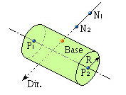
Project on a cylinder
P1: Coordinates of a point located on the central
axis of the Base Cylinder
P2: Coordinates of another point located on the central
axis of the Base Cylinder
Radius: Radius of the Base Cylinder
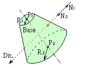
Project on a cone
P1: Coordinates of a point located on the central
axis of the Base Cone
P2: Coordinates of another point located on the central
axis of the Base Cone
Radius 1: Radius of the Base Cylinder at position
P1
Radius 2: Radius of the Base Cylinder at position
P2
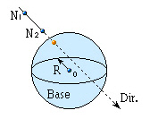
Project on a sphere
Origin: Coordinates of the center of the Base Sphere
Radius: Radius of the Base Sphere
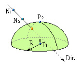
Project on an ellipsoid
P1: Coordinates of the center of the Base Ellipsoid's
bottom surface
P2: Coordinates of the top of the Base Ellipsoid
Radius: Radius of the circle at the bottom surface
of the Base Ellipsoid
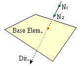
Project on an element
Element Number: Plate element number (Plane stress
element, plate element, etc.)
Direction
Assign the projection direction for the line or surface of the defined
projection base.
Normal:
Projection direction normal to the line or surface of the projection base
Direction Vector: Projection in an arbitrary direction.
Enter each of the x, y, z vector components in the projection direction.
Use either the keyboard or the mouse to assign the vector.
Divide
Create additional elements in between the
existing nodes and projected nodes along the lines of projection at either
equal or unequal spacings.
Equal:
Equal spacing
Number of
Divisions: Number of equal spacings
Parametric
Unequal: Unequal spacings defined in terms of distance ratios
Ratio:
Locations of division along the total projection length expressed in terms
of distance ratios (ex: 0.4, 0.6, 0.9)
Specify
a merging tolerance to merge newly created nodes and existing nodes.
 Extrude Elements
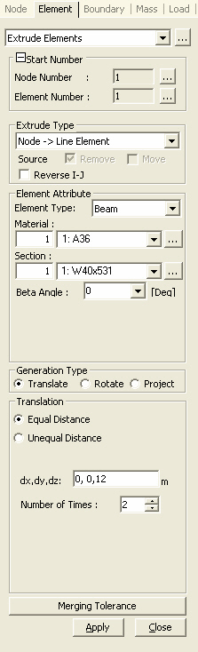
 to the right of
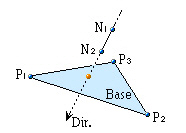
 Direction Vector: Projection in an arbitrary direction.
Enter each of the x, y, z vector components in the projection direction.
Use either the keyboard or the mouse to assign the vector.
Direction Vector: Projection in an arbitrary direction.
Enter each of the x, y, z vector components in the projection direction.
Use either the keyboard or the mouse to assign the vector. Divide