Enter
section properties for line elements (Truss, Tension-only, Compression-only,
Cable, Gap, Hook, Beam Element).
From the Main
Menu select Model > Properties > Section.
Select Geometry
> Properties > Section in the Menu tab of the Tree Menu.
Click Section in the Property Tool Bar.
Properties
(Section) dialog box
To
enter new or additional section properties
Click in the Properties
dialog box and enter the following: Enter the section properties by entry
types.
Modification
of previously entered section data
Select the section to be modified from the
list in the Section dialog box and click to modify the
related data.
Removal
of previously entered section data
Select the section to be deleted from the
list in the Section dialog box and click .
To
copy previously entered section data
Select the section to be copied from the
list in the Section dialog box and click .
To
modify section data from an existing fn.MCB file
Click and select the MCB
file containing the section data or specify a file name then click .[Details]
Section List Display section data contained in the existing fn.MCB file.
Selected
List Select section data to be imported and register them in the Selected List.
Note If a fn.MCB is selected, all the section data contained
in the existing fn.MCB file are registered in the Selected List.
Numbering
Type Specify the Import mode for section numbers.
Keep
ID Import the data keeping the same section numbers.
New
ID Assign new numbers to the imported section data.
To
modify previously entered section property numbers
Select the section property numbers to be
renumbered from the list in the Properties dialog box and modify the related
data followed by clicking . [Details]
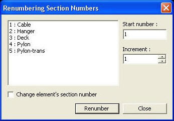
Renumbering Section Number dialog box
Start
number Assign a new starting number for the material to be modified.
Increment Enter the increment for numbering material property numbers.
Change
element's material number Modify a material property number. Using this option will modify the previously
defined material property number. If this option is not checked, the selected
material having previously defined number will become undefined and the
additional user-defined material number will be created without any assigned
elements.
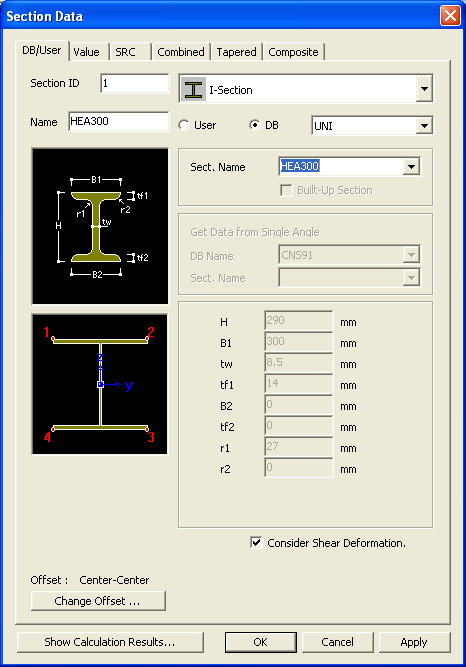
Section
Data Dialog
Section ID
Section
number (Auto-set to the last section number +1)
Note
Up to 999999 Section ID's
can be
assigned.
Name
Section
name (Sect. Name by default if not specified)
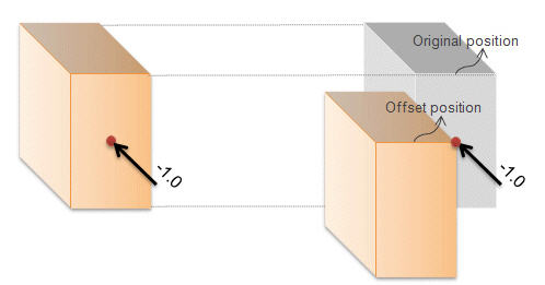
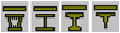
Offset
Display the section Offset currently set.
Location of the Centroid of a section is set as default. Click to
specify a section Offset away from the Centroid. Use Hidden
to verify the input.
Offset:
Specify the section Offset from the location options shown in the figure
below.
Horizontal
Offset: Specify the Offset in the transverse direction. "to
Extreme Fiber" assigns the offset to the outer-most point. For a
specific location of Offset, select 'User"and enter the distance
from the "Centroid" to the desired Offset location. Unless the
Offset is "Center-Center" the Horizontal Offset can be entered
as the "User" type. For a tapered (non-prismatic) section, data
input for the J-end also becomes activated.
Vertical
Offset: Specify the Offset in the vertical direction. "to
Extreme Fiber" assigns the offset to the outer-most point. For a
specific location of Offset, select "User" and enter the distance
from "Centroid" to the desired Offset location. Unless the Offset
is "Center-Center" the Vertical Offset can be entered as the
"User" type. For a tapered (non-prismatic) section, data input
for the J-end also becomes activated.
Note 1
When Offset
distance is specified, a positive (+) sign applies to Center-to-outward
for Centroid reference and Extreme-to-inward for Extreme Fiber reference.
User
Offset Reference: When section offset distance is specified as
the "User" type, define the reference location.
Centroid:
Specify the offset distance relative to the centroid of the section.
Extreme
Fiber(s): Specify the offset distance relative to Left/Right &
Top/Bottom.
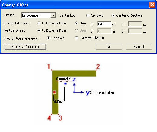
Note 2
When User type is specified, the Offset
distance and direction are entered relative to Centroid irrespective of
the Center option (Centroid or Center of Section). For example, specifying
"Offset: Left-Center", "Center Loc.: Center of Section"
and "Horizontal offset: 0.5 " User type" will result in
an Offset 0.5" to the left of the Centroid. And
if the Offset option is "Left-Center" and the Center option
is Center of Section the User type for Horizontal offset becomes activated
and the User type for Vertical offset becomes inactivated. The Horizontal
offset defined as User type here becomes the Centroid, and the Vertical
offset fixed to Center becomes the "Center of Section"
Note 3
When FCM Wizard is used, and "Apply
the Centroid of Pier Table Section Option" is selected, the node
locations of the girder will be changed as follows:
Offset: Center-Top
User Offset Reference: Extreme Fiber(s)
Vertical Offset: User, Offset Distance
(i & j) = Pier Table section height-Centroid of Pier Table section
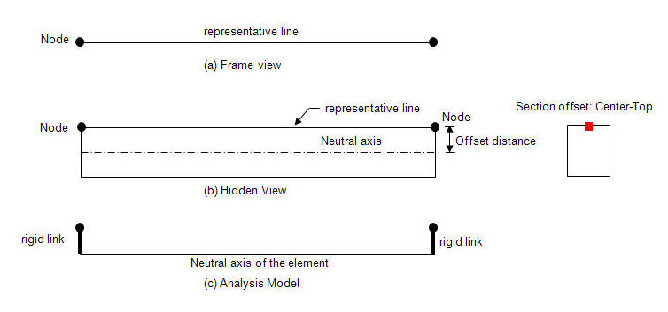
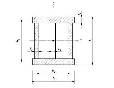
A beam element is defined by two nodes
and a line connecting the two nodes. This line becomes a reference line
representing the beam element, which usually coincides with the neutral
axis of the beam element. If a section offset is assigned to a section,
the neutral axis of the member shifts by the specified offset distance,
and the element reference line is placed at the offset location. The reference
line is used for selecting the element, assigning loads, displaying member
forces, etc. The offset of the neutral axis of the member relative to
the reference line in turn is reflected in analysis as shown in the figure
(c) below.
When an offset is assigned to a section,
a nodal load remains applied to the corresponding node regardless of the
offset. This results in moments due to the offset to the neutral axis
as shown in the case of figure b.
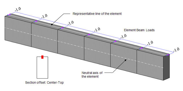
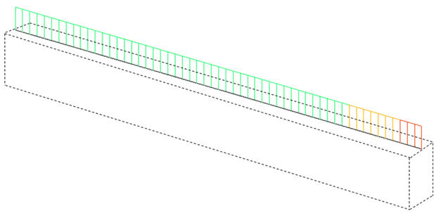
2. Element Beam Loads
Element beam load is applied to the neutral
axis of the element regardless of the section offset position. In the
diagram below, the element beam load is applied to the neutral axis even
though the section is offset from the reference line. Therefore torsional
moment from the element beam load is not induced by the offset. Note however
that the element beam load is displayed on the reference line as if it
is applied to the reference line, but it is actually applied to the neutral
axis.
Member forces (axial force, shear force,
moment & torsion) of a beam element are calculated relative to the
neutral axis. This is true even when a section offset is applied. However,
the member force diagrams are displayed on the reference line. This does
not mean the member forces are calculated relative to the reference line.
Member forces diagram when section offset is applied
An offset of a section can be defined
using the Beam End Offset function. For a prismatic section, a Section
offset is assigned to both
i-end and j-end identically. However,
Beam End Offset can assign different offsets at i-end and j-end independently.
Section offset is more useful for a tapered section as opposed to Beam
End Offset as shown in the figure below.
In addition, Section offset and Beam End
Offset cannot be assigned simultaneously. In such a case, Section offset
is ignored, and Beam End Offset only becomes effective.
Modeling of a tapered section group when a Section offset
(Center-Top) is defined
: Display the Offset specified from the Change Offset dialog
box in the guide diagram of Section Data window.
Consider Shear Deformation
Select whether to consider shear deformation.
This option will be applicable for structural analysis, but will not affect
the effective shear areas that appear by clicking .
Section Properties
Click to display the section
property data. The section property data table is either calculated from
the main dimensions or obtained from the DB depending on the method of
data entry.[Details]
Area:
Cross sectional area
Asy:
Effective Shear Area for shear force in the element's local y-direction
It
becomes inactive when Shear Deformation is not considered.
Asz:
Effective Shear Area for shear force in the element's local z-direction
It
becomes inactive when Shear Deformation is not considered.
Ixx:
Torsional Resistance about the element's local x-axis
Iyy:
Moment of Inertia about the element's local y-direction
Izz:
Moment of Inertia about the element's local z-direction
Cyp:
Distance from the section's neutral axis to the extreme fiber of the element
in the local (+)y-direction
Cym:
Distance from the section's neutral axis to the extreme fiber of the element
in the local (-)y-direction
Czp:
Distance from the section's neutral axis to the extreme fiber of the element
in the local (+)z-direction
Czm:
Distance from the section's neutral axis to the extreme fiber of the element
in the local (-)z-direction
Qyb:
Shear Coefficient for the shear force applied in the element's local z-direction
Qzb:
Shear Coefficient for the shear force applied in the element's local y-direction
Peri:
O: Total perimeter of the section
Peri:
I: Inside perimeter length of a hollow section
y1,
z1: Distance from the section's neutral axis to the Location 1
(used for computing combined stress)
y2,
z2: Distance from the section's neutral axis to the Location 2
(used for computing combined stress)
y3,
z3: Distance from the section's neutral axis to the Location 3
(used for computing combined stress)
y4,
z4: Distance from the section's neutral axis to the Location 4
(used for computing combined stress)
Zyy:
Plastic Section Modulus about the element local y-direction
Zzz:
Plastic Section Modulus about the element local z-direction
Note 1
All the above section property
data except for Area and Peri are required for beam elements.
Note 2
The shear deformations are
neglected if the effective shear areas are not specified. Cyp, Cym, Czp
and Czm are used to calculate the bending stresses. Qyb and Qzb are used
to calculate the shear stresses. Peri is used to calculate the Painting
Area.
Note 3
Zyy and Zzz are used to
calculate the strength for pushover analysis when Value Type Steel Section
has been assigned Design > Pushover Analysis > Define Hinge Properties.
Note
4 Element
Stiffness data
Sections can be defined
by the stiffness data entries even if the section dimensions (H, B1, ...
, etc.) are not entered.
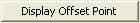
The cross-sectional area of a member is
used to compute axial stiffness and stress when the member is subjected
to a compression or tension force. Figure 1 illustrates the calculation
procedure.
Cross-sectional areas could be reduced
due to member openings and bolt or rivet holes for connections. midas
does not consider such reductions. Therefore, if necessary, the user is
required to modify the values using the option 2 above and his/her judgment.
Area = +dA = A1 + A2 +
A3
= (300 x 15) + (573 x 10) + (320 x 12)
= 14070
<Figure 1> Example of cross-sectional area calculation
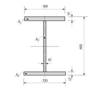
The effective shear areas of a member
are used to formulate the shear stiffness in the y- and z-axis directions
of the cross-section.
If the effective shear areas are omitted,
the shear deformations in the corresponding directions are neglected.
When midas computes the section properties
by the option 1 or 3, the corresponding shear stiffness components are
automatically calculated. Figure 2 outlines the calculation methods.
Asy:
Effective shear area in the ECS y-axis direction
Asz:
Effective shear area in the ECS z-axis direction
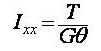
Torsional resistance refers to the stiffness
resisting torsional moments. It is expressed as
<Eq. 1>
where,
Ixx:
Torsional Constant
T: Torsional moment or torque
G: Shear Modulus of Elasticity
θ : Angle of twist
The torsional stiffness expressed in Eq.
1 must not be confused with the polar moment of inertia that determines
the torsional shear stresses. However, they are identical to one another
in the cases of circular or thick cylindrical sections.
No general equation exists to satisfactorily
calculate the torsional resistance applicable for all section types. The
calculation methods widely vary for open and closed sections and thin
and thick thickness sections.
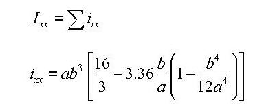
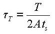
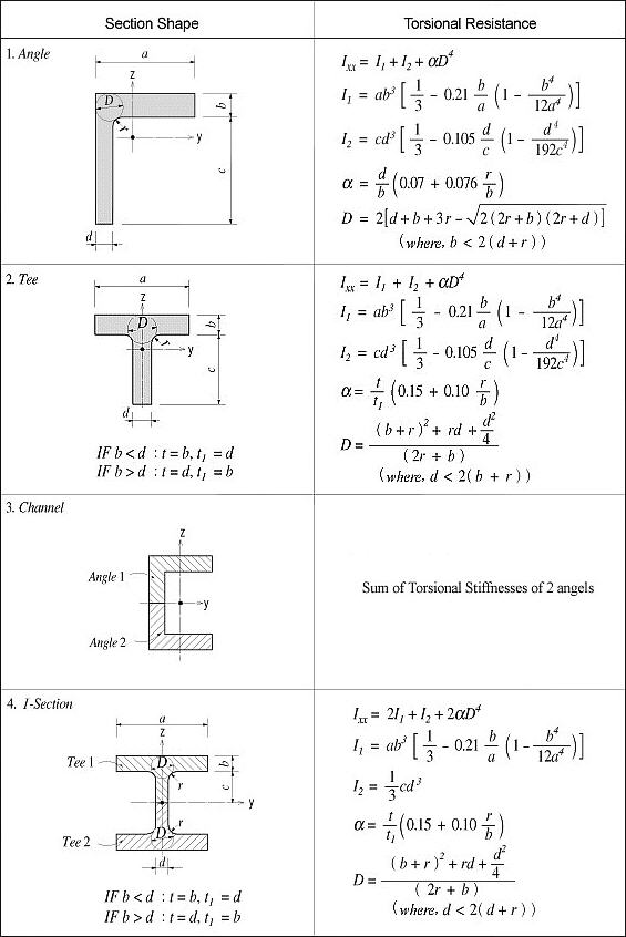
For calculating the torsional resistance
of an open section, an approximate method is used; the section is divided
into several rectangular sub-sections and then their resistances are summed
into a total resistance, Ixx, calculated by the equation below.
<Eq. 2>
for a e b
where,
Ixx:
Torsional resistance of a (rectangular) sub-section
2a: Length of the longer side of a sub-section
2b: Length of the shorter side of a sub-section
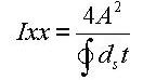
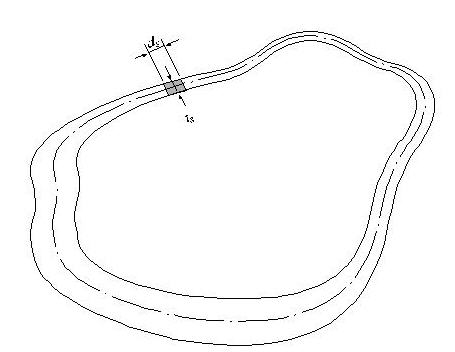
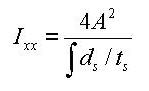
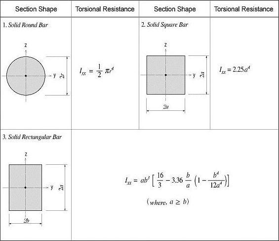
Figure 3 illustrates the equation for
calculating the torsional resistance of a thin walled, tube-shaped, closed
section.
<Eq. 3>
where,
A: Area enclosed by the mid-line of the
tube
ds:
Infinitesimal length of thickness centerline at a given point
t: Thickness of tube at a given point
For those sections such as bridge box
girders, which retain the form of thick walled tubes, the torsional stiffness
can be obtained by combining the above two equations, Eq. 1 and Eq. 3.
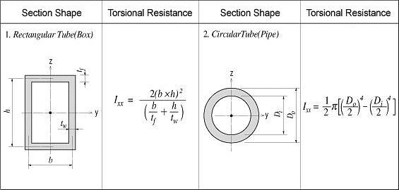
Torsional
resistance:
Shear stress at a given point:
Thickness of tube at a given point:
<Figure 3> Torsional
resistance of a thin walled, tube-shaped, closed section
<Figure 4> Torsional resistance of solid sections
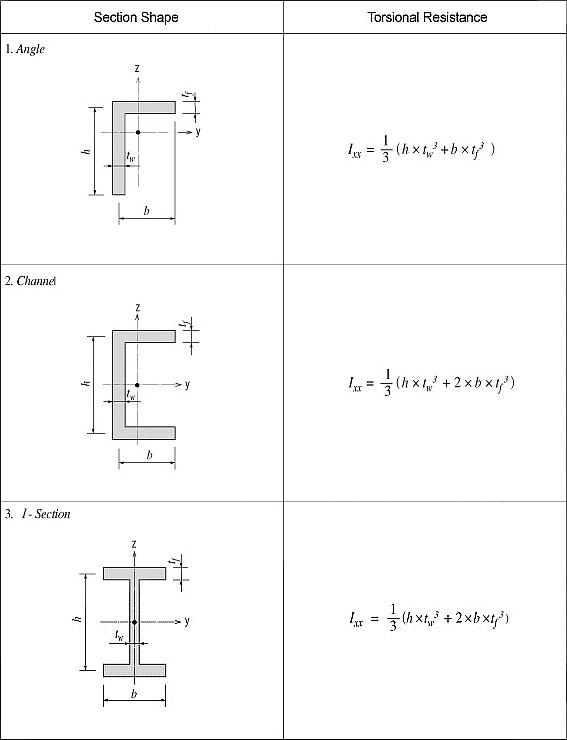
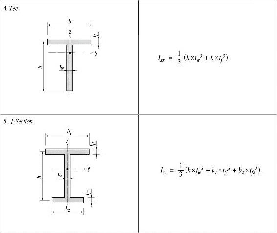
<Figure 5> Torsional resistance of thin walled,
closed sections
<Figure 6> Torsional resistance of thick walled,
open sections
<Figure 7> Torsional resistance of thin walled,
open sections
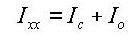
In practice, combined sections often exist.
A combined built-up section may include both closed and open sections.
In such a case, the stiffness calculation is performed for each part,
and their torsional stiffnesses are summed to establish the total stiffness
for the built-up section.
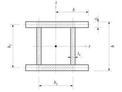
For example, a double I-section shown
in Figure 8(a) consists of a closed section in the middle and two open
sections, one on each side.
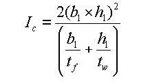
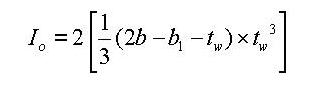
Figure 8(b) shows a built-up section made
up of an I-shaped section reinforced with two web plates, forming two
closed sections. In this case, the torsional resistance for the section
is computed as follows:
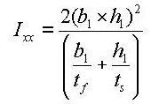
If the torsional resistance contributed
by the flange tips is negligible relative to the total section, the torsional
property may be calculated solely on the basis of the outer closed section
(hatched section) as expressed in Eq. 7.
<Eq. 7>
If
the torsional resistance of the open sections is too large to ignore,
then it should be included in the total resistance.
(a) Section consisted of closed and open sections
(b) Section consisted of two closed sections
<Figure 8> Torsional resistance of built-up sections
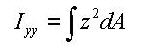
The area moment of inertia is used to
compute the flexural stiffness resisting bending moments. It is calculated
relative to the centroid of the section.
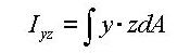
The area product moment of inertia is
used to compute stresses for non-symmetrical sections, which is defined
as follows:
<Eq. 10>
Sections that have at least one axis of
symmetry produce Iyz=0.
Typical symmetrical sections include I, pipe, box, channel and tee shapes,
which are symmetrical about at least one of their local axes, y and z.
However, for non-symmetrical sections such as angle shaped sections, where
Iyz`0,
the area product moment of inertia should be considered for obtaining
stress components.
The area product moment of inertia for
an angle is calculated as shown in Figure 10.
<Figure 10> Area product moment of inertia for an
angle
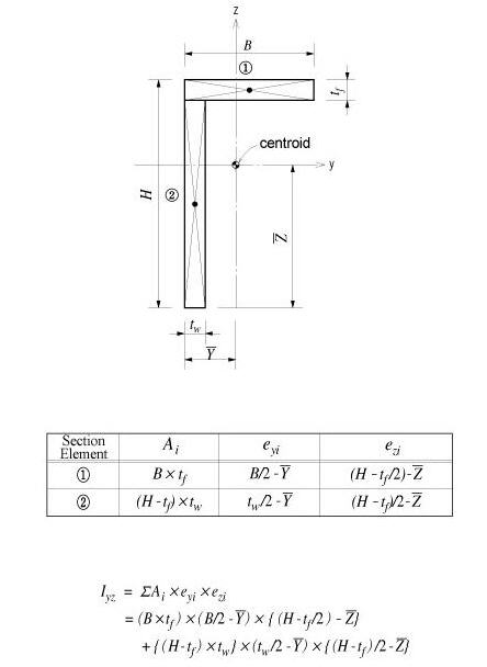
<Figure 11> Bending stress distribution of a non-symmetrical
section
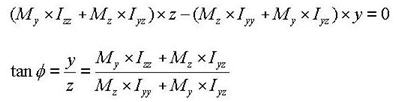
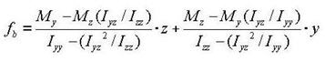
The neutral axis represents an axis along
which bending stress is 0 (zero). As illustrated in the right-hand side
of Figure 11, the n-axis represents the neutral axis, to which the m-axis
is perpendicular. Since the bending stress is zero at the neutral axis,
the direction of the neutral axis can be obtained from the relation defined
as
<Eq. 11>
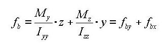
The following represents a general equation
applied to calculate the bending stress of a section:
<Eq. 12>
In the case of an I shaped section, Iyz=0, hence the
equation can be simplified as:
<Eq. 13>
where,
Iyy: Area moment of inertia about the
ECS y-axis
Izz: Area moment of inertia about the
ECS z-axis
Iyz: Area product moment of inertia
y: Distance from the neutral axis to the
location of bending stress calculation in the ECS y-axis direction
z: Distance from the neutral axis to the
location of bending stress calculation in the ECS z-axis direction
My: Bending moment about the ECS y-axis
Mz: Bending moment about the ECS z-axis
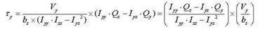
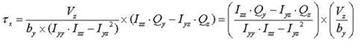
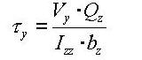
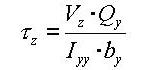
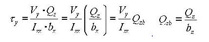
The general expressions for calculating
shear stresses in the ECS y and z-axes are:
<Eq. 14>
<Eq. 15>
where,
Vy: Shear force in the ECS y-axis direction
Vz: Shear force in the ECS z-axis direction
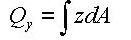
Qy: First moment of area about the ECS
y-axis
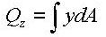
Qz: First moment of area about the ECS
z-axis
by: Thickness of the section at which
a shear stress is calculated, in the direction normal to the ECS z-
axis
bz: Thickness of the section at which
a shear stress is calculated, in the direction normal to the ECS y-axis
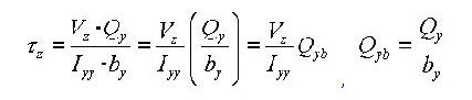
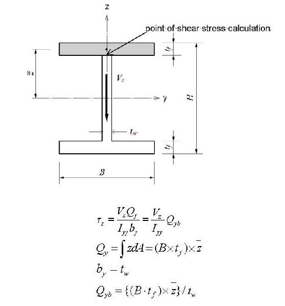
The shear factor is used to compute the
shear stress at a particular point on a section, which is obtained by
dividing the first moment of area by the thickness of the section.
midas calculates the stiffness for a full
composite action of structural steel and reinforced concrete. Reinforcing
bars are presumed to be included in the concrete section. The composite
action is transformed into equivalent section properties.
The program uses the elastic moduli of
the steel (Es) and concrete (Ec) defined in the SSRC79 (Structural Stability
Research Council, 1979, USA) for calculating the equivalent section properties.
In addition,
the Ec value is decreased by 20% in accordance with the EUROCODE 4.
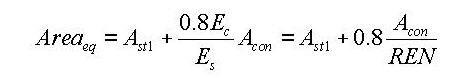
- Equivalent cross-sectional area
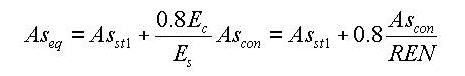
- Equivalent effective shear area
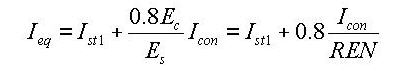
- Equivalent area moment of inertia
where,
Ast1:
Area of structural steel
Acon:
Area of concrete
Asst1:
Effective shear area of structural steel
Ascon:
Effective shear area of concrete
Ist1:
Area moment of inertia of structural steel
Icon:
Area moment of inertia of concrete
REN: Modular ratio (elasticity modular
ratio of the structural steel to the concrete, Es/Ec)
- Equivalent torsional coefficient
Note 5
Determining the positions
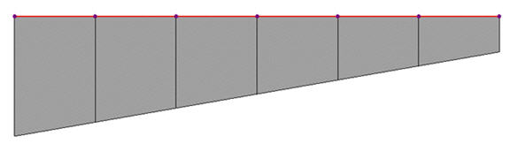
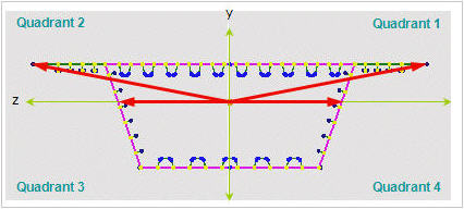
of y1~4, z1~4 of a section imported from SPC[Details]
1. Divide the section into four quadrants.
2. Assign the positions furthermost from
the centroid in each quadrant for checking stresses.
If the webs of a section are extensively
sloped as in the above diagram, the points furthermost from the centroid
may not be the lowest points of the section. Use caution that the stress
checking positions of quadrants 3 & 4 may be selected differently
from the expectation.
User:
Enter the main dimensions of a standardized section shape.
H, B1, ...: Refer to the dimension information
diagram in the dialog box.
DB:
Select a section from the DB of the standard sections for a country.
AISC2K(US):
American Institute of Steel Construction, 2000 US Unit : lb, in
AISC2K(SI):
American Institute of Steel Construction, 2000 SI Unit : kN, m, mm
AISC:
American Institute of Steel Construction
CISC02(US):
Canadian Institute of Steel Construction (US Unit : lb, in)
CISC02(SI):
Canadian Institute of Steel Construction (SI Unit : kN, m, mm)
BS(S):
British Standard
Note
BS indicates BS4-1 revised prior to 1993.
BS4
- 93: British Standard / BS 4-1 : 1993
DIN:
Deutches Institut fur Normung e.v
UNI:
Italian National Standard
Revision of Gen 2012
GOST:
Russian National Standard
STO_ASChM:
Russian National Standard
JIS2K
: Japanese Industrial Standards 2000
JIS:
Japanese Industrial Standards
KS:
Korean Industrial Standards
GB-YB05:
Guojia Biao Zhun-Yejin Bu Biao Zhun
Pacific(SI):
Bentley Pacific Standards (SI Unit : kN, m, mm)
IS84:
Indian Standards
GB-YB05:
Guojia Biao Zhun-Yejin Bu Biao Zhun(2005)
CNS91:
Taiwan Standards
Sect. Name: Enter directly a DB section
name or select a desired DB from the Section list. When the section name
is directly entered, it must correspond to the format of the DB section
names.
Note When specifying Double Angle or Double Channel sections, assign the sectional
shape in the list and select User. Then, select DB and Sect. Name from
Get Data from Single Angle (or Channel) or directly enter the main dimensions
of the section.
The section data can be entered by the
following 3 methods in the dialog box:
1. Select a section from the DB (database)
of the standard sections for a country.
2. Enter the main dimensions of a standardized
section shape.
3. Import
a section generated from SPC module.
Section Shape List:
Assign a section shape to use.
Built-Up
Section: Fabricated section
Note Check in the case of a built-up section and leave it blank in the case
of a rolled steel section. The data is referred to for strength verification
for steel members and compiling material quantities in BOM.
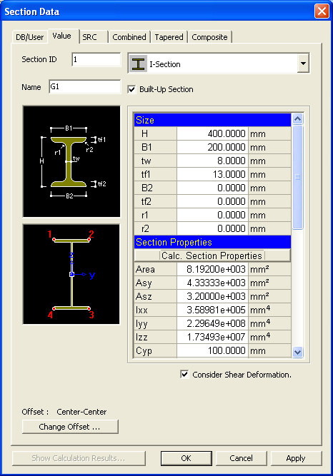
Size
H, B1,
...: Refer to the diagram denoting section dimensions in the dialog
box.
The structure can be analyzed only with
the stiffness data even if the section dimensions are not specified.
Section Properties
The main section dimensions entered in
Size are used to calculate and display the section stiffness.
Area: Cross sectional area
Asy:
Effective Shear Area for shear force in the element's local
y-direction
It becomes inactive when Shear Deformation
is not considered.
Asz:
Effective Shear Area for shear force in the element's local z-direction
It becomes inactive when Shear Deformation
is not considered.
Ixx:
Torsional Resistance about the element's local x-axis
Iyy:
Moment of Inertia about the element's local y-direction
Izz:
Moment of Inertia about the element's local z-direction
Cyp:
Distance from the section's neutral axis to the extreme fiber of the element
in the local (+)y-direction
Cym:
Distance from the section's neutral axis to the extreme fiber of the element
in the local (-)y-direction
Czp:
Distance from the section's neutral axis to the extreme fiber of the element
in the local (+)z-direction
Czm:
Distance from the section's neutral axis to the extreme fiber of the element
in the local (-)z-direction
Qyb:
Shear Coefficient for the shear force applied in the element's local z-direction
Qzb:
Shear Coefficient for the shear force applied in the element's local y-direction
Peri:O:
Total perimeter of the section
Peri:I:
Inside perimeter length of a hollow section
Note The value of Peri:I is '0' for an I-shaped section since the section is
not hollow.
Cent:y:
Centroidal distance in ECS y-axis
Cent:z:
Centroidal distance in ECS z-axis
y1,
z1: Distance from the section's neutral
axis to the Location 1 (used for computing combined stress) The user may
specify
the location of the stress display.
y2,
z2: Distance from the section's neutral
axis to the Location 2 (used for computing combined stress) The user may
specify
the location of the stress display.
y3,
z3: Distance from the section's neutral
axis to the Location 3 (used for computing combined stress) The user may
specify
the location of the stress display.
y4,
z4: Distance from the section's neutral
axis to the Location 4 (used for computing combined stress) The user may
specify
the location of the stress display.
Zyy:
Plastic Section Modulus about the element local y-direction
Zzz:
Plastic Section Modulus about the element local z-direction
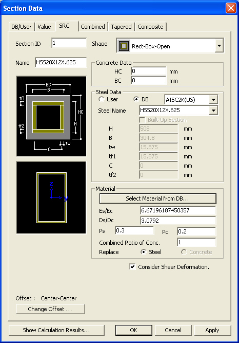
Enter the section property data for steel
RC composite members in the dialog box.
Shape:
Assign a section shape to use.
Note
New Cross I
Section and Combined T-Section were incorporated.
ConcreteData: Enter the outer dimensions
of the RC section of a steel-encased concrete section.
Steel
Data: Enter the steel section data.
User:
Enter the main dimensions of a standardized section shape.
H, B1,
...: Refer to the dimension information diagram in the dialog box.
DB:
Select a section from the DB of the standard sections for a country.
AISC2K(US):
American Institute of Steel Construction, 2000 US Unit : lb, in
AISC2K(SI):
American Institute of Steel Construction, 2000 SI Unit : kN, m, mm
AISC:
American Institute of Steel Construction
CISC02(US):
Canadian Institute of Steel Construction (US Unit : lb, in)
CISC02(SI):
Canadian Institute of Steel Construction (SI Unit : kN, m, mm)
BS(S):
British Standard
Note
BS indicates BS4-1 revised prior to 1993.
BS4
- 93: British Standard / BS 4-1 : 1993
DIN(S):
Deutches Institut fur Normung e.v
JIS2K
: Japanese Industrial Standards 2000
JIS:
Japanese Industrial Standards
KS:
Korean Industrial Standards
GB-YB:
Guojia Biao Zhun-Yejin Bu Biao Zhun
Pacific(SI):
Bentley Pacific Standards (SI Unit : kN, m, mm)
IS84:
Indian Standards
CNS91:
Taiwan Standards
Steel Name: Enter directly a DB section
name or select a desired DB from the Section list. When the section name
is directly entered, it must correspond to the format of the DB section
names.
In this dialog box, enter the section
properties for a combined section made up by two standard section types.
User: Enter
the main dimensions of standardized section shapes.
DB: Select
the sections from the DB of the standard sections for a country.
AISC2K(US):
American Institute of Steel Construction, 2000 US Unit : lb, in
AISC2K(SI):
American Institute of Steel Construction, 2000 SI Unit : kN, m, mm
AISC:
American Institute of Steel Construction
CISC02(US):
Canadian Institute of Steel Construction (US Unit : lb, in)
CISC02(SI):
Canadian Institute of Steel Construction (SI Unit : kN, m, mm)
BS(S):
British Standard
Note
BS indicates BS4-1 revised prior to 1993.
BS4 - 93:
British Standard / BS 4-1 : 1993
DIN(S):
Deutches Institut fur Normung e.v
JIS2K :
Japanese Industrial Standards 2000
JIS:
Japanese Industrial Standards
KS:
Korean Industrial Standards
GB-YB:
Guojia Biao Zhun-Yejin Bu Biao Zhun
Pacific(SI):
Bentley Pacific Standards (SI Unit : kN, m, mm)
IS84:
Indian Standards
CNS91:
Taiwan Standards
Data 1, Data 2:
Enter the section data for individual components constituting the combined
section.
Sect. Name:
Enter directly a DB section name or select a desired DB from the Section
list. When the section name is directly entered, it must correspond to
the format of the DB section names.
In this dialog box, enter the section
properties for both ends of a line element to define a non-uniform section
(Non-prismatic Section/ Tapered Section) of identical shape.(Refer to
Note)
Section Shape List:
Applicable tapered section shapes are shown below. For
PSC, Composite Type or General Section of Value type, pre-defined sections
can be brought in from the Section DB.
DB/User:
All sections except for the R-Octagon section
Value:
All sections except for the R-Octagon section
Value:
Assign value when the user directly enters the section stiffness data.
Enter the section dimensions for section-i
and j separately and click . Then, the user may modify the
auto-calculated stiffness data or directly enter the stiffness data without
entering the section dimensions.
User:
Enter the main dimensions of standardized section shapes.
DB:
Select the sections from the DB of the standard sections for a country.
AISC2K(US):
American Institute of Steel Construction, 2000 US Unit : lb, in
AISC2K(SI):
American Institute of Steel Construction, 2000 SI Unit : kN, m, mm
AISC:
American Institute of Steel Construction
CISC02(US):
Canadian Institute of Steel Construction (US Unit : lb, in)
CISC02(SI):
Canadian Institute of Steel Construction (SI Unit : kN, m, mm)
BS(S):
British Standard
DIN(S):
Deutches Institut fur Normung e.v
JIS2K
: Japanese Industrial Standards 2000
JIS:
Japanese Industrial Standards
KS:
Korean Industrial Standards
GB-YB:
Guojia Biao Zhun-Yejin Bu Biao Zhun
Pacific(SI):
Bentley Pacific Standards (SI Unit : kN, m, mm)
IS84:
Indian Standards
CNS91:
Taiwan Standards
Section-i, Section-j:
Enter directly each section name corresponding to the starting section-i
and the ending section-j or select the desired DB from the section list
to describe the tapered section. When the section names are directly entered,
they must correspond to the DB section name format.
y Axis Variation:
Dimensional variation affects the moment of inertia about the element
local y-axis along the length.
z Axis Variation:
Dimensional variation affects the moment of inertia about the element
local z-axis along the length.
Linear:
linear variation along the element local x-direction
Parabolic:
parabolic variation along the element local x-direction
Cubic:
cubic variation along the element local x-direction
Note 1
Calculation
of section properties as per Dimensional Variation[Details]
Once the main section dimensions of both
ends of a tapered section member are entered, the section properties are
considered to vary from the i end (element connection node N1) to the
j end (element connection node N2) along the member length. The cross
sectional areas, effective shear areas and torsional resistances are assumed
to vary linearly from i to j along the element local x-axis. The moments
of inertia are assumed to vary linearly, parabolically or cubically depending
on the directions of section changes.
For instance, in the figures below, the
variations of Iyy
and Izzcan be expressed as follows:
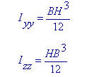
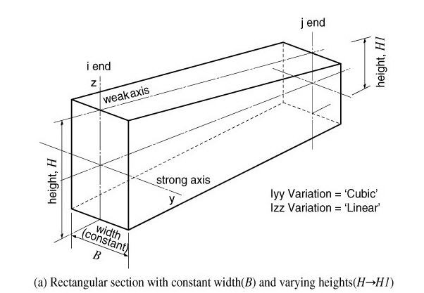
Moments of Inertia about strong and weak
axes for a rectangular section <See figure below>
When the width (B) is constant and the
height (H) varies, the moments of inertia show a cubic variation about
the strong axis and a linear variation about the weak axis. Namely, Iyy Variation
= 'Cubic', IzzVariation = 'Linear'.
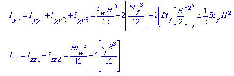
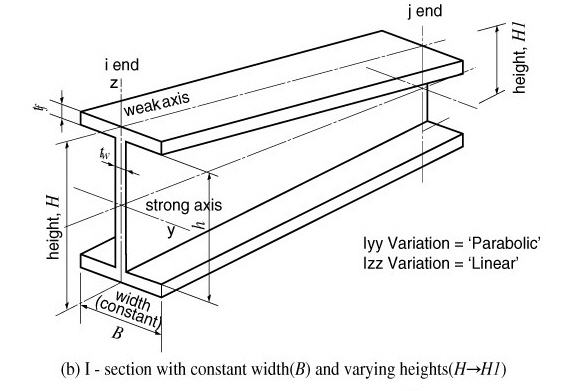
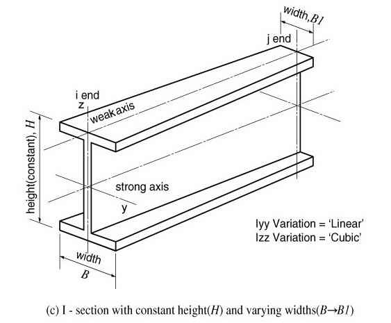
Moments of Inertia about strong and weak
axes for an I-section <See figure below>
When the width (B) is constant and the
height (H) varies, the moment of inertia about the strong axis shows a
nearly parabolic variation if the 1st and 2nd terms are neglected in the
above equation. The moment of inertia about the weak axis varies almost
linearly. Hence, it is feasible to use Iyy
Variation = 'Parabolic', IzzVariation = 'Linear'. On the other hand,
when the height (H) is constant and the width (B) varies, the moment of
inertia about the strong axis varies almost linearly and the moment of
inertia about the weak axis shows a nearly cubic variation. Hence, it
is feasible to use Iyy
Variation = 'Linear', Izz Variation
= 'Cubic'.
Entry
of section data for a tapered section member
Note 2
In
the results produced in contours, diagrams and tables, dimensional variation
in the axial direction affects the moment of inertia only. In Beam Detail
Analysis, section properties are directly calculated at 1/4, 1/2 and 3/4
points using the shape information. As such, dimensional variation affects
all the section properties (A, Asy, Asz, Ixx, Iyy & Izz).
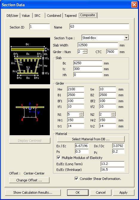
In
this dialog box, the sectional data pertaining to the "Analysis considering
the section variation before and after composite actions in Composite
Bridges" are specified.
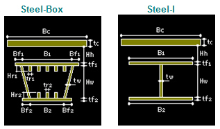
Section
Type: Assign a section type
Steel-Box:
Structural steel Box Girder
Steel -I:
Structural Steel I Shape Girder
User:
Section properties defined as General Section in the Value Tab
Slab Width / Girder
Num. & CTC
Slab Width:
Total width of slab (used for calculating lateral flexure stiffness after
becoming composite)
Girder
Num.:
Number of girders within the total slab
CTC:
Center to center spacing between girders
Note 1
In case when the number of girders is 1 in
a structure, enter 1 for Number of girders (Num) and enter 0 for center
to center spacing (CTC).
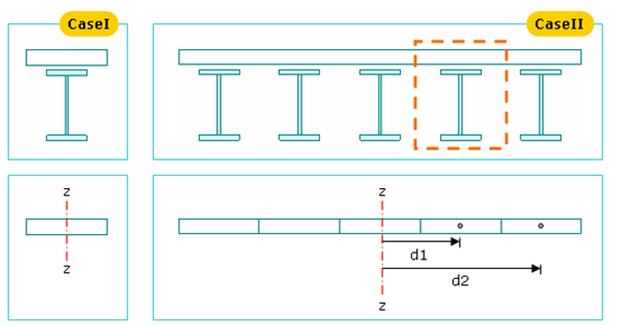
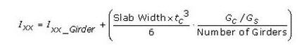
If
a slab width and girder data are entered where a number of girders
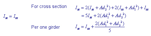
exist, the program assumes that the slab acts as a rigid body and increases
the moment of Inertia about the vertical direction (Izz). This
concept is shown in Case I and Case II below.
In case of a separate section as in Case I
and in case of a rigid body section as in Case II, Izz is calculated as
below.
Slab
Bc:
Effective slab width for one girder
tc:
Thickness of slab
Hh:
Distance from the top of girder to the underside of slab
If "User" is selected in Section
Type, select Before & After Composite sections.
Section
Select the section data to be applied s
Before/After Composite sections from the section data already defined
under other tabs such as DB/User, Value, ect.
Material
Click [Select
Material from DB...] button to select the material properties for
steel and concrete stored in the DB for a country. The following items
are automatically entered.
Es/Ec:
ModulusRatio, steel to concrete
Ds/Dc:
Density ratio, steel to concrete
Note
For the calculation of section properties
of Composite Section, concrete is converted into steel. The self-weight
is computed as follows:
The Weight of Composite Section = Steel
Weight + Concrete Weight
If Ds/Dc = 0, concrete weight is ignored and
only steel weight is considered.
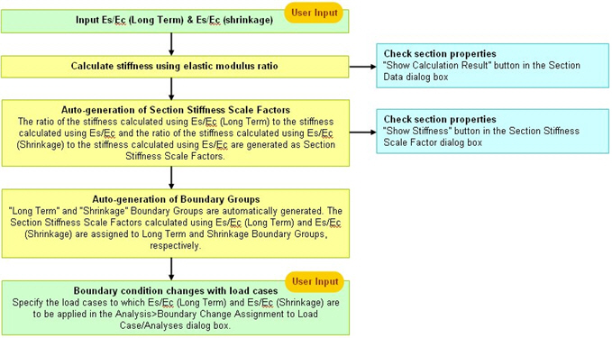
Recalculate the modulus
of elasticity of slab concrete to calculate the stresses due to creep
and shrinkage. Multiple elastic modulus ratios need to be inputted into
an identical section for different load cases. Application of this to
analyses and stress checks is specified in EN1994-2 (Eurocode4: Design
of composite steel and concrete structures, Part 2) 5.4.2.2.
By checking on this
option and entering Es/Ec(Long Term) and Es/Ec(shrinkage), the section
properties for post-composite section with those modulus ratios taken
into account are calculated.
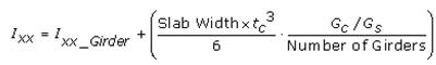
The value Ixx of the
post-composite section is calculated based on the shear modulus ratio
(Gs/Gc), not the elastic modulus ratio (Es/Ec). When Es/Ec is entered
from DB, Poisson's Ratios from DB are used for the calculation of Gs and
Gc. When Es/Ec is inputted by the user, Poisson's Ratio is set to 0.
 Section
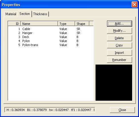
 in the Properties
dialog box and enter the following: Enter the section properties by entry
types.
in the Properties
dialog box and enter the following: Enter the section properties by entry
types. to modify the
related data.
to modify the
related data. .
. .
. and select the MCB
file containing the section data or specify a file name then click
and select the MCB
file containing the section data or specify a file name then click  .
. .
. 
 Section ID
 to
specify a section Offset away from the Centroid. Use
to
specify a section Offset away from the Centroid. Use  Hidden
to verify the input.
Hidden
to verify the input. 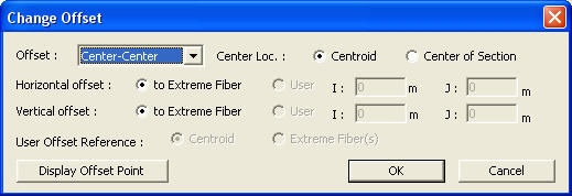
 : Display the Offset specified from the Change Offset dialog
box in the guide diagram of Section Data window.
: Display the Offset specified from the Change Offset dialog
box in the guide diagram of Section Data window.  .
. 

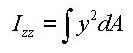
 : area
 : distance from the reference
point to the centroid of the section element in the z-axis direction
: distance from the reference
point to the centroid of the section element in the z-axis direction : distance from the reference
point to the centroid of the section element in the y-axis direction
: distance from the reference
point to the centroid of the section element in the y-axis direction : first moment of area
relative to the reference point in the y-axis direction
: first moment of area
relative to the reference point in the y-axis direction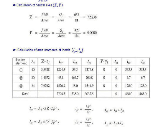

 to select the material
properties for steel and concrete stored in the DB for a country. The
following items are automatically entered:
to select the material
properties for steel and concrete stored in the DB for a country. The
following items are automatically entered: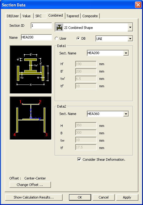
 Revision of Gen 2010
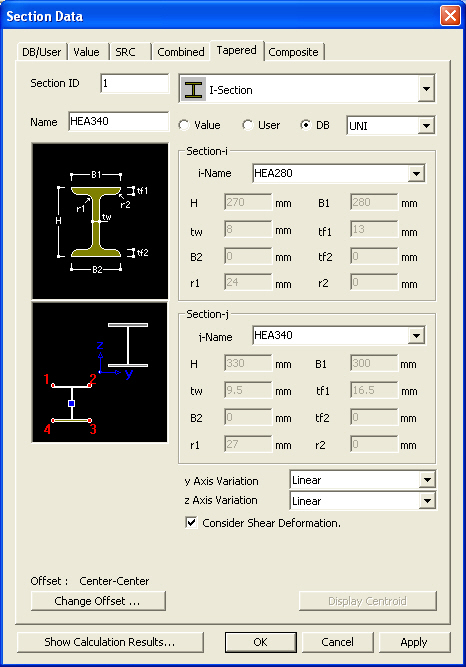


 . Then, the user may modify the
auto-calculated stiffness data or directly enter the stiffness data without
entering the section dimensions.
. Then, the user may modify the
auto-calculated stiffness data or directly enter the stiffness data without
entering the section dimensions.