Beam End Offsets Table
|
|
|
|
|
|
Enter or modify Rigid End Offset Distance data or Joint Eccentricity data in GCS or the element's local coordinate system of beam elements in a spreadsheet format Table.
Table Tool in midas offers a variety of powerful built-in functions.
Refer to the following items for detail directions: Usage of Table Tool
Terminology
Familiarize with Usage
Basic directions (Cell motion, selection, size control, etc.)
Data manipulation (Add, delete, modify data, etc.)
Copy/Paste data using clipboard
Supplementary Table functions
Table Sorting
Table format setting
Auto-fit column width
Graph printing
Supplementary functions by Table types
Node/Element Table
Results Table |
|
|
|
|
|
|
|
From the Main Menu select Model > Boundaries > Beam End Offset Table.
Select Structure Tables > Boundaries > Beam End Offsets in the Tables tab of the Tree Menu. |
|
|
|
|
|
(Refer to "Beam End Offsets")
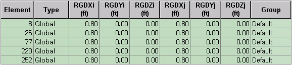
Refer to Usage of Table Tool and enter or modify the following data:
Element: Element number
Type: Define a reference coordinate system (Global, Element)
In case of Type = "Global"
RGDXi: Vector component of the end offset distance at N1 end in GCS X-direction
RGDYi: Vector component of the end offset distance at N1 end in GCS Y-direction
RGDZi: Vector component of the end offset distance at N1 end in GCS Z-direction
RGDXj: Vector component of the end offset distance at N2 end in GCS X-direction
RGDYj: Vector component of the end offset distance at N2 end in GCS Y-direction
RGDZj: Vector component of the end offset distance at N2 end in GCS Z-direction
For Type = "Element"
RGDXi: End offset distance in the element's local (+) x-direction at N1 end
RGDXj: End offset distance in the element's local (-) x-direction at N2 end
Group: Boundary Group in which the entered boundary conditions are included
|
|
|