|
|
Click  to the right of
Node Local Axis: Display the Node
Local Axis Table to the right of
Node Local Axis: Display the Node
Local Axis Table
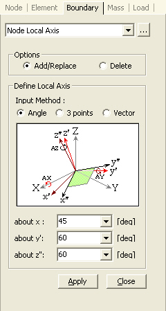
 Options Options
Add/Replace:
Enter or replace a local coordinate system for selected nodes
Delete:
Delete previously entered node's local coordinate system for selected
nodes
Define Local Axis
Input Method:
Select a method of specifying the node's local coordinate system.
Angle:
Specify 3 angles of rotation to define the node's local coordinate system
about x:
Angle of rotation about GCS X-axis
about y:
Angle of rotation about y'-axis rotated about X-axis
about z:
Angle of rotation about z"-axis rotated about X- and y'-axes |
3 points:
Specify 3 nodal coordinates to define the node's local coordinate system
 P0: Coordinates of the origin of the node's local
coordinate system P0: Coordinates of the origin of the node's local
coordinate system
P1: Coordinates of an arbitrary node on the node's
local x-axis
P2: Coordinates of a node moved from P1, parallel
to the node's local y-axis
Vector:
Specify 2 vectors to define the node's local coordinate system
V1: x-direction vector starting from the origin of
the node's local coordinate system
V2: Vector starting from the origin of the node's
local coordinate system to the point P2 of the 3 points method above
Note
The following are the application functions for Node Local Axis:
"Supports"
"Point Spring Supports"
"General Spring Supports"
"Surface Spring Supports" (in
case of Convert to Point Spring)
"Specified Displacements of Supports"
"Reaction Forces/Moments" of "Reactions"
"Reactions" of "Influence
Lines"
"Reactions" of "Influence
Surfaces"
|