Generate a regular mesh for the area defined by four nodes.
From the Main Menu
select Model > Mesh
> Map-mesh 4-Node Area.
Select Geometry >
Mesh > Map-mesh 4-Node Area in the Menu
tab of the Tree
Menu.
Click Auto-mesh
Planar Area in the Icon
Menu.
New
for Gen2010
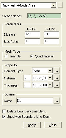
Corner
Nodes
Consecutively select four nodes to define
a rectangular mesh area clockwise or counterclockwise. The direction of
selection determines the normal direction of the generated mesh elements.
Parameters
Division:
The number of divisions in each direction
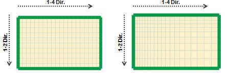
Bias Ratio:
The ratio of the first mesh element to the last mesh element
When Bias Ratio is 1, When
Bias Ratio is 4,
Mesh Type
Triangle : Generate
a mesh using triangular elements.
Quadrilateral : Generate
a mesh using quadrilateral elements.
Property
Element Type
Select the element type of the planar mesh
elements to be created. There are four element types available: Plate,
Plane Stress, Plane Strain and Axisymmetric. The button
to the right becomes active when the element type is Plate or Plane Stress.
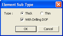
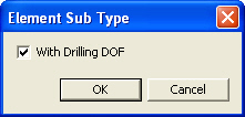
Click the button to define the Element Sub Type.
Sub-type of plate element Sub-type
of plane stress element
Material
: Enter the material property of the planar mesh elements to be created.
Click to the right to invoke the Material dialog box.
Thickness
: Enter the thickness data of the planar mesh elements to be created.
Click to
the right to invoke the Thickness dialog box.
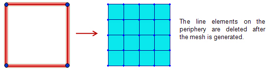
If this option is selected,
the line elements on the periphery of the mesh area are deleted after
the mesh is generated.
Subdivide
Boundary Line Elem.
This option can be used
when ‘Delete Boundary Line Elem.’ is not selected. If this option
is selected, the line elements on the periphery of the mesh area are divided
according to the mesh size. The divided line elements are registered as
a Member and it can be checked in the Member
Assignment dialog.


 Corner
Nodes
Corner
Nodes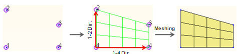
 button
to the right becomes active when the element type is Plate or Plane Stress.
Click the button to define the Element Sub Type.
button
to the right becomes active when the element type is Plate or Plane Stress.
Click the button to define the Element Sub Type.