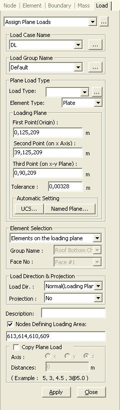
Assign Plane Loads
| ||||||||||||||
|
| ||||||||||||||
|
| ||||||||||||||
|
Apply the plane loads defined in (Plane Load Type) to any specific locations on plate or solid elements.
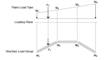
Plane Load is the function to assign specific load type defined by the user on plate or solid elements. This function is especially useful for assigning specific load type to various locations such as equipment load. After defining the load type and magnitude in Define Plane Load Type, select the specific locations to which load is assigned in Assign Plane Loads.
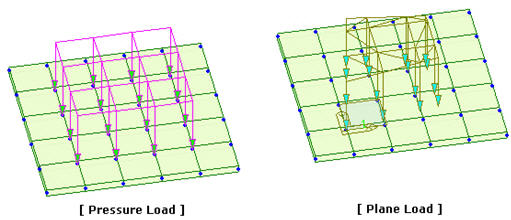
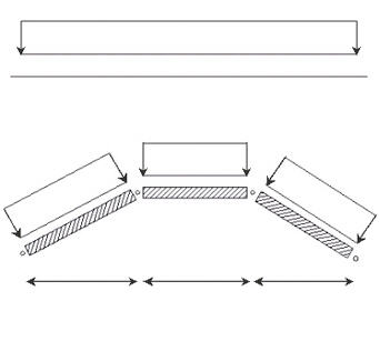
Pressure Load is assigned to entire elements. On the other hand, the user can freely define Plane Load independent of the division of elements as shown in the figure below. This function is convenient since the locations of nodes for which a load is assigned need not be considered. Entered load will be converted to adjacent nodal loads based on the stiffness of elements.
| ||||||||||||||
|
| ||||||||||||||
|
| ||||||||||||||
|
| ||||||||||||||
|
From the Main Menu select Load > Assign Plane Loads.
Select Static Loads > Assign Plane Loads in the Menu tab of the Tree Menu. | ||||||||||||||
|
| ||||||||||||||
|
| ||||||||||||||
|
Note Defined by 3 Points: 1st Point represents the origin and 2nd Point defines the direction in x-axis. Defined by X-Y Plane: X, Y coordinates '0' becomes the origin, and x, y-axes are defined to coincide with the global coordinate system (GCS). Defined by X-Z Plane: X, Z coordinates '0' becomes the origin, and GCS X & Z-axes become x & y-axes respectively. Defined by Y-Z Plane: Y, Z coordinates '0' becomes the origin, and GCS Y & Z-axes become x & y-axes respectively.
| ||||||||||||||
 to the right
to prompt the Static Load Cases dialog box to add, modify or delete load
cases.
to the right
to prompt the Static Load Cases dialog box to add, modify or delete load
cases. 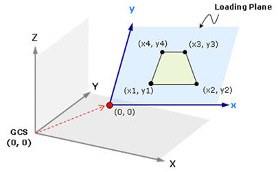
 use the
predefined Named UCS as the plane coordinate system
use the
predefined Named UCS as the plane coordinate system use the
predefined Named Plane as the plane coordinate system
use the
predefined Named Plane as the plane coordinate system|
Figure 1. Locations and magnitudes of Plane Loads
|
|
|
|
|
|
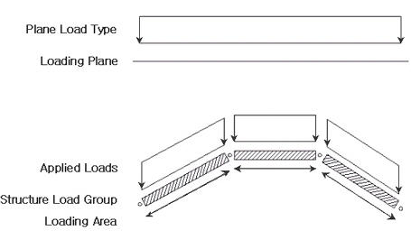
Load Dir. : Normal (Loading Plane)
Project : No |
Load Dir. : Normal (Element)
Project : No, Load Direction |
|
|
|
|
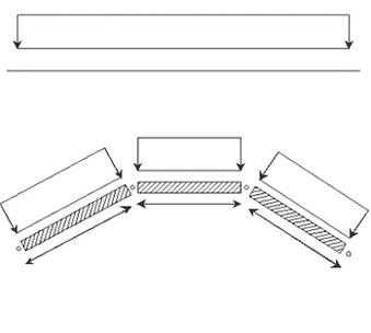
Load Dir. : Normal (Loading Plane)
Project : Load Direction, Loading Plane |
Load Dir. : Normal (Element)
Project : Loading Plane |
|
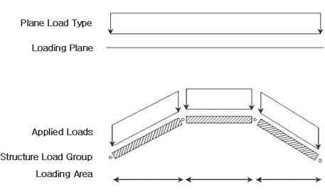
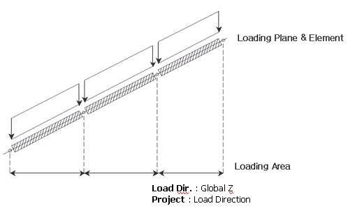
Load Dir. : Global Z
Project
: Load Direction Figure 2. Load Direction & Projection |
|
Global X: apply the loads in the GCS X-direction
Global Y: apply the loads in the GCS Y-direction
Global Z: apply the loads in the GCS Z-direction
Projection
Yes: apply the plane loads on the projected plane area normal to the direction of the load application
No: apply the plane loads over the entire loaded area
For example, on a sloped roof, snow load will be projected 'Yes' and dead load will not be projected 'No'.
Description
Enter a brief description.
 Nodes
Defining Loading Area
Nodes
Defining Loading Area
Define the range of the loaded area for the
plane loads.
Assign the node numbers of the corners constituting the loaded range sequentially
in a rotational direction. Once the loaded range is
defined, only the defined plane loads falling within the range are applied. If a range is undefined, all the plane loads defined in Plane
Load Type will be applied. Using the Mouse editor on the model window can also define the corner nodes by picking the points
sequentially. The assignment of the range becomes completed upon selecting the first corner point again.
 Copy Plane Load
The specified plane loads can be repeatedly copied at the intervals of your choice in the same magnitudes.
Axis: copy direction
x: x-direction in GCS or UCS
y: y-direction in GCS or UCS
z: z-direction in GCS or UCS
Distances: copy distances
Multiple distances can be specified to copy the plane loads repeatedly.