Enter the hydrostatic pressure (fluid potential) loads at the edges
or faces of Plate, Plane Stress, Plane Strain or Solid Elements.
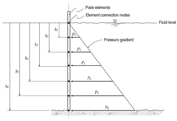
The hydrostatic pressure loads are calculated at each corner node of
the elements. The point pressure is obtained by multiplying the distance
from the given surface of the fluid by the density of the fluid.
Pressure loads due to the fluid potential at the connection
nodes of plate elements
From the Main
Menu select Load
> Hydrostatic Pressure Loads.
Select Static Loads
> Hydrostatic Pressure Loads in the Menu tab of the
Tree Menu.
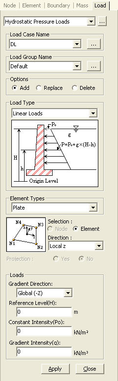
Load
Case Name
Assign the load case
name. Click to the right to enter additional load cases
and modify or delete existing load cases.
Load
Group Name
Select the desire Load
Group that will include the entered Hydrostatic Pressure Loads Data. Select
"Defualt", if a Group assignment is unnecessary. Click to the right to add, modify or delete Load Groups.
Options
Add:
Enter new or additional hydrostatic pressures
Select the type of elements
to be subjected to pressure loads. Refer to the figure at the bottom to
assign the loading direction and the loaded side(s).
Plate:
plate element
Selection:
Select loaded objects by either nodes or elements
Direction
Local
x: Pressure loads applied in the element local x-direction
Local
y: Pressure loads applied in the element local y-direction
Local
z: Pressure loads applied in the element local z-direction
Global
X: Pressure loads applied in GCS X-direction
Global
Y: Pressure loads applied in GCS Y-direction
Global
Z: Pressure loads applied in GCS Z-direction
Plane Strain:
plane strain element
Axisymmetric:
axisymmetric element
Pressure
Edge: Refer to the figure to select the edge numbers to be loaded.
8 Nodes
Solid: 8 node solid element
6 Nodes
Solid: 6 node solid element
4 Nodes
Solid: 4 node solid element
Pressure
Face: Refer to the figure to select the face number to be loaded.
Direction
Normal:
Pressure loads applied normally to the face of the solid elements
Global
X: Pressure loads applied in GCS X-direction
Global
Y: Pressure loads applied in GCS Y-direction
Global
Z: Pressure loads applied in GCS Z-direction
Projection
When the pressure loads are applied to plate
or solid elements in the direction of 'Global
X, Y or Z', select whether or not to
project the loads on a plane perpendicular
to the loading direction.
Yes:
project the pressure loads
No:
the pressure loads are applied along the entire face
Loads
The application conditions for hydrostatic
pressure loads are as follows:
Hydrostatic
Pressure = P0
+ g(H - h)
Where, H
> h (position of the element connection nodes)
Gradient
Direction: Assign the gradient direction of the hydraulic potential
- increasing direction from the fluid surface
Global ( -X )
Global ( -Y )
Global ( -Z )
Reference Level(H): Reference level for the pressure
due to the hydraulic potential of fluids (enter with the mouse or keyboard)
Constant
Intensity(P0):
Pressure acting on the fluid surface
Gradient
Intensity(g): Specific weight of fluid
Lateral
soil pressure with or without ground water pressure can be applied using
this functionality.
Note
When lateral soil pressure is entered as Hydrostatic Pressure Loads, Element
Type must be Plate, and the structure must be divided into a reasonable
number of elements to properly reflect its flexural behavior.
Direction represents the
direction of acting force. Gradient Direction is generally selected in
the direction of gravity (Global-Z).
Constant Intensity (Po)
represents surcharge (soil overburden), which is subject to soil pressure
coefficient. Gradient Intensity (g) is also obtained by applying the soil
pressure coefficient. Depending on the presence of ground water, the following
is entered:
1) Only soil is present
without ground water
Soil: g = soil pressure
coefficient * unit density of soil
2) To consider ground water
(separately enter values for soil and water)
Soil: g = soil pressure
coefficient * unit density of soil under water
Water: g = unit density
of water
(In case of water, Reference
level (H) locates the level of ground water.)
 Load
Case Name
Load
Case Name to the right to enter additional load cases
and modify or delete existing load cases.
to the right to enter additional load cases
and modify or delete existing load cases. Reference Level(H)