Enter the method of performing moving load analysis and the location
of output for element results.
From the Main
Menu select Analysis
> Moving Load Analysis Control.
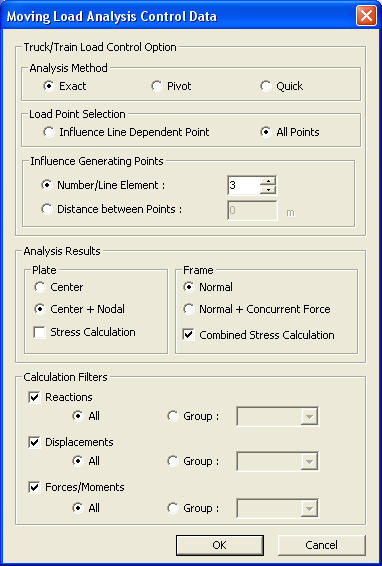
Moving Load Analysis Control Data dialog box
Truck/Train Load Control Option
Set the method of performing moving load
analysis using vehicular loads and the method of applying loads.
Analysis
Method
Set the moving load analysis method.
Load Point
Selection Method
Set the selection method for application location of vehicular loads.
Influence
Dependent Point
This is a method which controls the vehicular loads in a moving load analysis
according to the influence values.
Maximum
value(+): From the locations of the applied loads only the loads
that result in positive influence values are used in the computation.
Minimum
value(-): From the locations of the applied loads, only the loads
that result in negative(-) influence values are used in the computation.
This method is used for general vehicular
loading and yields results larger than that from the All Points method
because the loads are controlled according to the influence values.
All Points
This is a method which analyzes the structure for applied vehicular loads
in the moving load analysis at all locations without controling the influence
values.
The method is used for train loading and
yields results smaller than that from the Influence Dependent Point method
because the loads are not controlled according to the influence values.
Influence
Generating Point No. / Line Element
Assign the number of reference points on a line element for moving loads
and drawing influence line in an influence line analysis.
The accuracy of results increases with the
increase in the number, but the analysis time may be excessive. If the
length of beam element assigned with traffic line lane or plate elements
assigned with traffic surface lane is large, then the Influence Generating
Point No. / Line Element?should be increased for more accurate analysis.
Analysis Position
Set the position of the elements for which
the moving load analysis results are calculated.
Plate
For plate elements, member forces per unit length are calculated as a result
of moving load analysis. The form of member force results is selected
from below.
Center:
Calculate the member forces per unit length with respect to the centers
of the elements and the output results are produced for the entire elements.
Center
+ Nodal: Calculate the member forces per unit length with respect
to the element centers and the nodes constituting the elements and produce
the results accordingly.
Stress
Calculation: Assign whether or not to calculate the stresses of
plate elements.
Frame
The moving load analysis results for Frame elements are produced in the
form of member forces pertaining to 5 Points of each member. The form
of member forces is selected from below.
Normal:
Output member forces with respect to 5 Points of each beam element.
Normal
+ Concurrent Force: Calculate the member forces at 5 Points of
the beam elements. Calculate the corresponding moments under the conditions
where the maximum and minimum axial forces occur at each position. Similarly,
calculate the corresponding axial forces under the conditions where the
maximum and minimum moments occur at each position. The results are then
produced. To produce the results in a table format, go to Result Tables
> Beam > Force, right-click and select View by Max Value Item.
Combined Stress Calculation:
Calculation Filters
Select the nodes or elements to be included
in the moving load analysis.
Reactions
Select and enter the supports where the moving load analysis results related
to reactions are to be obtained.
All:
Select all supports.
Group:
Use the Group identified in the model, and enter the supports in the Group.
Displacements
Select and enter the nodes where the moving load analysis results related
to displacements are to be obtained.
All:
Select all supports.
Group:
Use Group to enter nodes.
Forces/Moments
Select and enter the elements where the moving load analysis results related
to member forces are to be obtained.
 Truck/Train Load Control Option