Member Diagrams
| ||||||||||
|
| ||||||||||
|
| ||||||||||
|
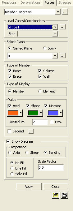
Overall member forces (axial, shear and bending moment) in a specified plane can be simultaneously checked by each member (Column, Beam, Brace and Wall).
Note | ||||||||||
|
| ||||||||||
|
| ||||||||||
|
| ||||||||||
|
From the Main Menu select Results > Forces > Member Diagrams
Select Results > Forces > Member Diagrams in the Menu tab of the Tree Menu. | ||||||||||
|
| ||||||||||
|
| ||||||||||
|
 to the right of Load Cases/Combinations in the dialog box
to add new or modify or delete existing load combinations. (Refer to "
to the right of Load Cases/Combinations in the dialog box
to add new or modify or delete existing load combinations. (Refer to "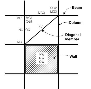
|
Legend |
Display various references related to analysis results to the right or left of the working window.
Element numbers pertaining to the maximum and minimum forces are displayed. |
|
|
Legend Position: Position of the legend in the display window
Rank Value Type: Specify a type of values in the Legend and the number of decimal points |
 Show Diagram
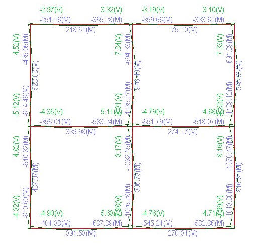
Define the type of display for Member (force) Diagram.
Component
Axial
Shear
Bending
No Fill: Display only the outline representing the magnitudes of the member forces.
Line Fill: Display the diagram filled in with color lines.
Solid Fill: Display the diagram filled in with color surfaces.
Scale: Drawing scale for member forces.
Batch Output Generation (  ,
,  )
)
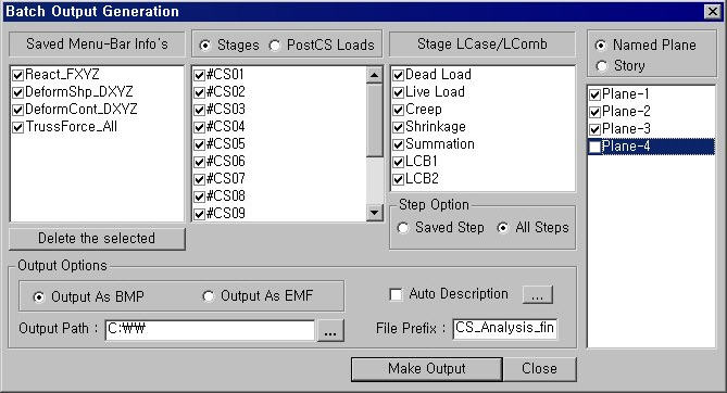
Given the types of analysis results for Graphic outputs, generate consecutively graphic outputs for selected load cases and combinations.
|
|
Assign a Base File Name under which the types of results (selection data in the Batch Output Generation dialog box for graphic outputs) are stored. |
|
|
Specify the Base Files to perform Batch Output Generation, planes, etc in the following dialog box.
Saved Menu-Bar Info's: Listed here are the Base Files. Select the Base File Names for Batch Output.
When the construction stage analysis is carried out, all the construction stages are listed. We simply select the stages of interests to be included in the batch output. If no construction stage analysis is performed, the column in the dialog box becomes inactive and lists load (combination) conditions.
Stages The results output of all the construction stages are produced. The construction stages are listed below.
PostCS Loads The results output for only the Final Stage are produced. The construction stages are listed below. If no construction stage analysis is performed, the load (combination) conditions are listed.
Use Saved Apply only the (saved) step or load (combination) condition selected at the time of creating each Base File.
Stage LCase/LComb When the construction stage analysis is carried out, the auto-generated construction stage load conditions and the additionally entered construction stage load combinations are listed. Check on only the load (combination) conditions that will be used to produce batch outputs. This column becomes inactive if Final Stage Loads?is selected or no construction stage analysis is carried out.
Step Option Specify the steps for which the outputs will be produced when the construction stage analysis or large displacement geometric nonlinear analysis is performed.
Saved Step: Use only the steps used for creating the Base Files
All Steps: Use all the steps
Named Plane: Select Planes that will be used to produce batch graphic output.
Story: Specify Stories that will be used to produce batch graphic output.
Output Options
Output As BMP Select a Graphic File type as BMP.
Output As EMF Select a Graphic File type as EMF.
Auto Description: At the top left of the Graphic Outputs produced in batch, auto-generate and include the notes such as the types and components of the analysis results, construction stages and steps, load (combination) conditions, etc. The font size, color, type, etc. can be changed upon clicking the button .
Output Path Specify the path for saving the graphic files to be produced in batch.
File Prefix: Specify the prefix of the Graphic Files to be created. The filenames will be consisted of "Prefix"_"Base File Name"_"Load Comb.".bmp(emf) or "Prefix"_"Base File Name"_"Stage"_"Stage LCase"_"Step".bmp(emf).
Produce the contents of data input in the Base Files and Batch Output Generation dialog box in a binary type file (fn.bog). Click the button and select a fn.bog to use the same output format.
Note Import /Export is only meaningful for different projects. In a given structural model, the Base Files are automatically stored and listed. |
 : Delete all the Base Files selected with the mouse.
 : Produce the specified batch Graphic Files reflecting the
contents of the dialog box.
: Produce the specified batch Graphic Files reflecting the
contents of the dialog box. /
/ 