Modify Steel Material
| |||||||||||||||||||||||||||||||||||||||||||||||||||||||||||||||||||||||||||||||||||||||||||||||||||||||||||||||||||||||||||||||||||||||||||||||||||||||||||||||||||||||||||||||||||||||||||||||||||||||||||||||||||||||||||||||||||||||||||||||||||||||||||||||||||||||||||||||||||||||||||||||||||||||||||||||||||||||||||||||||||||||||||||||||||||||||||||||||||||||||||||||||||||||||||||||||||||||||||||||||||||||||||||||||||||||||||||||||||||||||||||||||||||||||||||||||||||||||||||||||||||||||||||||||||||||||||||||||||||||||||||||||||||||||||||||||||||||||||||||||||||||||||||||||||||||||||||||||||||||||||||||||||||||||||||||||||||||||||||||||||||||||||||||||||||||||||||||||||||||||||||||||||||||||||||||||||||||||||||||||||||||||||||||||||||||||||||||||||||||||||||||||||||||||||||||||||||||||||||||||||||||||||||||||||||||||||||||||||||||||||||||||||||||||||||||||||||||||||||||||||||||||||||||||||||||||||||||||||||||||||||||||||||||||||||||||||||||||||||||||||||||||||||||||||||||||||||||||||||||
|
Use this function to modify a part of the steel material property data entered during the creation of the analysis model or to change the entered material property data pertaining to specific design requirements. | |||||||||||||||||||||||||||||||||||||||||||||||||||||||||||||||||||||||||||||||||||||||||||||||||||||||||||||||||||||||||||||||||||||||||||||||||||||||||||||||||||||||||||||||||||||||||||||||||||||||||||||||||||||||||||||||||||||||||||||||||||||||||||||||||||||||||||||||||||||||||||||||||||||||||||||||||||||||||||||||||||||||||||||||||||||||||||||||||||||||||||||||||||||||||||||||||||||||||||||||||||||||||||||||||||||||||||||||||||||||||||||||||||||||||||||||||||||||||||||||||||||||||||||||||||||||||||||||||||||||||||||||||||||||||||||||||||||||||||||||||||||||||||||||||||||||||||||||||||||||||||||||||||||||||||||||||||||||||||||||||||||||||||||||||||||||||||||||||||||||||||||||||||||||||||||||||||||||||||||||||||||||||||||||||||||||||||||||||||||||||||||||||||||||||||||||||||||||||||||||||||||||||||||||||||||||||||||||||||||||||||||||||||||||||||||||||||||||||||||||||||||||||||||||||||||||||||||||||||||||||||||||||||||||||||||||||||||||||||||||||||||||||||||||||||||||||||||||||||||||
|
| |||||||||||||||||||||||||||||||||||||||||||||||||||||||||||||||||||||||||||||||||||||||||||||||||||||||||||||||||||||||||||||||||||||||||||||||||||||||||||||||||||||||||||||||||||||||||||||||||||||||||||||||||||||||||||||||||||||||||||||||||||||||||||||||||||||||||||||||||||||||||||||||||||||||||||||||||||||||||||||||||||||||||||||||||||||||||||||||||||||||||||||||||||||||||||||||||||||||||||||||||||||||||||||||||||||||||||||||||||||||||||||||||||||||||||||||||||||||||||||||||||||||||||||||||||||||||||||||||||||||||||||||||||||||||||||||||||||||||||||||||||||||||||||||||||||||||||||||||||||||||||||||||||||||||||||||||||||||||||||||||||||||||||||||||||||||||||||||||||||||||||||||||||||||||||||||||||||||||||||||||||||||||||||||||||||||||||||||||||||||||||||||||||||||||||||||||||||||||||||||||||||||||||||||||||||||||||||||||||||||||||||||||||||||||||||||||||||||||||||||||||||||||||||||||||||||||||||||||||||||||||||||||||||||||||||||||||||||||||||||||||||||||||||||||||||||||||||||||||||||
|
From the Main Menu select Design > Steel Design Parameter > Modify Steel Material.
From the Menu tab of the Tree Menu select Design > Steel Design Parameter > Modify Steel Material. | |||||||||||||||||||||||||||||||||||||||||||||||||||||||||||||||||||||||||||||||||||||||||||||||||||||||||||||||||||||||||||||||||||||||||||||||||||||||||||||||||||||||||||||||||||||||||||||||||||||||||||||||||||||||||||||||||||||||||||||||||||||||||||||||||||||||||||||||||||||||||||||||||||||||||||||||||||||||||||||||||||||||||||||||||||||||||||||||||||||||||||||||||||||||||||||||||||||||||||||||||||||||||||||||||||||||||||||||||||||||||||||||||||||||||||||||||||||||||||||||||||||||||||||||||||||||||||||||||||||||||||||||||||||||||||||||||||||||||||||||||||||||||||||||||||||||||||||||||||||||||||||||||||||||||||||||||||||||||||||||||||||||||||||||||||||||||||||||||||||||||||||||||||||||||||||||||||||||||||||||||||||||||||||||||||||||||||||||||||||||||||||||||||||||||||||||||||||||||||||||||||||||||||||||||||||||||||||||||||||||||||||||||||||||||||||||||||||||||||||||||||||||||||||||||||||||||||||||||||||||||||||||||||||||||||||||||||||||||||||||||||||||||||||||||||||||||||||||||||||||
|
| |||||||||||||||||||||||||||||||||||||||||||||||||||||||||||||||||||||||||||||||||||||||||||||||||||||||||||||||||||||||||||||||||||||||||||||||||||||||||||||||||||||||||||||||||||||||||||||||||||||||||||||||||||||||||||||||||||||||||||||||||||||||||||||||||||||||||||||||||||||||||||||||||||||||||||||||||||||||||||||||||||||||||||||||||||||||||||||||||||||||||||||||||||||||||||||||||||||||||||||||||||||||||||||||||||||||||||||||||||||||||||||||||||||||||||||||||||||||||||||||||||||||||||||||||||||||||||||||||||||||||||||||||||||||||||||||||||||||||||||||||||||||||||||||||||||||||||||||||||||||||||||||||||||||||||||||||||||||||||||||||||||||||||||||||||||||||||||||||||||||||||||||||||||||||||||||||||||||||||||||||||||||||||||||||||||||||||||||||||||||||||||||||||||||||||||||||||||||||||||||||||||||||||||||||||||||||||||||||||||||||||||||||||||||||||||||||||||||||||||||||||||||||||||||||||||||||||||||||||||||||||||||||||||||||||||||||||||||||||||||||||||||||||||||||||||||||||||||||||||||
|
Use the following dialog box to enter the data (refer to Note 1):
Modify Steel Material dialog box
|
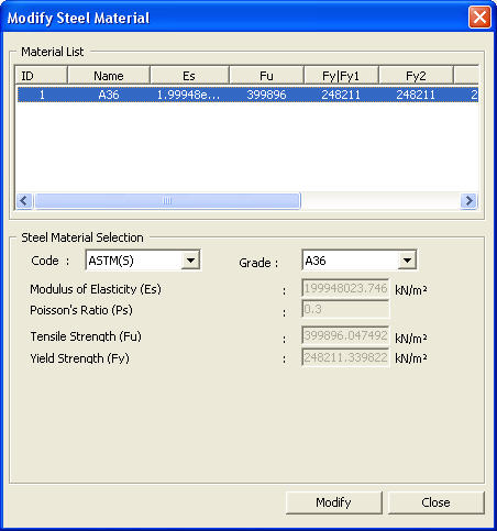
 Material List
 : Modify the relevant
material property data by replacing with the values entered by the user.
: Modify the relevant
material property data by replacing with the values entered by the user. : Do not enter the values
or the selection and close the dialog box.
: Do not enter the values
or the selection and close the dialog box.|
Material type |
Fy-a |
|
A36 |
36. |
|
A53 |
35. |
|
A242-40 |
40. |
|
A242-42 |
42. |
|
A242-46 |
46. |
|
A242-50 |
50. |
|
A441-40 |
40. |
|
A441-42 |
42. |
|
A441-46 |
46. |
|
A441-50 |
50. |
|
A500-33 |
33. |
|
A500-39 |
39. |
|
A500-42 |
42. |
|
A500-46 |
46. |
|
A500-50 |
50. |
|
A501 |
36. |
|
A514-90 |
90. |
|
A514-100 |
100. |
|
A529-42 |
42. |
|
A529-50 |
50. |
|
A570-40 |
40. |
|
A570-42 |
42. |
|
A572-42 |
42. |
|
A572-50 |
50. |
|
A572-60 |
60. |
|
A572-65 |
65. |
|
A588-40 |
40. |
|
A588-42 |
42. |
|
A588-46 |
46. |
|
A588-50 |
50. |
|
A606-45 |
45. |
|
A606-50 |
50. |
|
A607-45 |
45. |
|
A607-50 |
50. |
|
A607-55 |
55. |
|
A607-60 |
60. |
|
A607-65 |
65. |
|
A607-70 |
70. |
|
A618-50 |
50. |
|
A852 |
70. |
(2)
CSA(S)
- Es = 200000 N/mm2
- Fy (N/mm2)
|
Material type |
Fy-1 |
Fy-2 |
Fy-3 |
|
230G(H) |
230. |
230. |
230. |
|
350G(H) |
350. |
350. |
350. |
|
400G(H) |
400. |
400. |
400. |
|
260W(H) |
260. |
260. |
260. |
|
300W(H) |
300. |
290. |
280. |
|
350W(H) |
350. |
330. |
320. |
|
380W(H) |
380. |
380. |
380. |
|
400W(H) |
400. |
400. |
400. |
|
480W(H) |
480. |
480. |
480. |
|
260WT(H) |
260. |
260. |
260. |
|
300WT(H) |
300. |
290. |
290. |
|
350WT(H) |
350. |
330. |
330. |
|
380WT(H) |
380. |
380. |
380. |
|
400WT(H) |
400. |
400. |
400. |
|
480WT(H) |
480. |
480. |
480. |
|
350R(H) |
350. |
350. |
350. |
|
350A(H) |
350. |
350. |
350. |
|
400A(H) |
400. |
400. |
400. |
|
480A(H) |
480. |
480. |
480. |
|
350AT(H) |
350. |
350. |
350. |
|
400AT(H) |
400. |
400. |
400. |
|
480AT(H) |
480. |
480. |
480. |
|
700Q(H) |
700. |
700. |
700. |
|
700QT(H) |
700. |
700. |
700. |
|
230G(C) |
230. |
230. |
230. |
|
350G(C) |
350. |
350. |
350. |
|
400G(C) |
400. |
400. |
400. |
|
260W(C) |
260. |
260. |
260. |
|
300W(C) |
300. |
290. |
280. |
|
350W(C) |
350. |
330. |
320. |
|
380W(C) |
380. |
380. |
380. |
|
400W(C) |
400. |
400. |
400. |
|
480W(C) |
480. |
480. |
480. |
|
260WT(C) |
260. |
260. |
260. |
|
300WT(C) |
300. |
290. |
290. |
|
350WT(C) |
350. |
330. |
330. |
|
380WT(C) |
380. |
380. |
380. |
|
400WT(C) |
400. |
400. |
400. |
|
480WT(C) |
480. |
480. |
480. |
|
350R(C) |
350. |
350. |
350. |
|
350A(C) |
350. |
350. |
350. |
|
400A(C) |
400. |
400. |
400. |
|
480A(C) |
480. |
480. |
480. |
|
350AT(C) |
350. |
350. |
350. |
|
400AT(C) |
400. |
400. |
400. |
|
480AT(C) |
480. |
480. |
480. |
|
700Q(C) |
700. |
700. |
700. |
|
700QT(C) |
700. |
700. |
700. |
- Max. thickness for applying Fy (mm)
Hollow Structural Sections
|
Material type |
Fy-1 |
Fy-2 |
Fy-3 |
|
300W |
16.0 |
|
|
|
350W, 350WT |
16.0 |
|
|
|
380W, 380WT |
16.0 |
|
|
|
350A, 350AT |
16.0 |
|
|
Plates, Bars and Welded Shapes
|
Material type |
Fy-1 |
Fy-2 |
Fy-3 |
|
350R |
14.0 |
|
|
|
400W, 400WT |
20.0 |
|
|
|
480W, 480WT |
20.0 |
|
|
|
480A, 480AT |
20.0 |
|
|
|
350G, 400G |
30.0 |
|
|
|
400A, 400AT |
40.0 |
|
|
|
700Q, 700QT |
50.0 |
|
|
|
350WT |
40.0 |
60.0 |
100.0 |
|
260W, 260WT |
40.0 |
65.0 |
100.0 |
|
300W, 300WT |
40.0 |
65.0 |
100.0 |
|
350W, 350WT |
40.0 |
65.0 |
100.0 |
|
350A, 350AT |
40.0 |
65.0 |
100.0 |
|
230G |
40.0 |
65.0 |
300.0 |
Rolled Shapes and Sheet Piling (G=Group)
|
Material type |
Fy-1 |
Fy-2 |
Fy-3 |
|
350R |
G1 |
|
|
|
400W |
G1 |
|
|
|
480W, 480WT |
G1 |
|
|
|
400WT |
G1,2 |
|
|
|
400A, 400AT |
G1,2 |
|
|
|
300W |
G1,2 |
G3 |
|
|
350G, 400G |
G1,2 |
G3 |
|
|
350WT |
G1,2 |
G3,4 |
|
|
260W |
G1,2 |
G3,4 |
|
|
230G |
G1,2 |
G3,4 |
G5 |
|
260WT, 300WT |
G1,2 |
G3,4 |
G5 |
|
350A, 350AT |
G1,2 |
G3,4 |
G5 |
(3)
BS(S)
- Es = 205000 N/mm2
- Fy (N/mm2)
|
Material type |
Fy-a |
Fy-b |
Fy-c |
Fy-d |
|
43A |
275. |
265. |
255. |
245. |
|
43B |
275. |
265. |
255. |
245. |
|
43B(T) |
275. |
265. |
255. |
245. |
|
43C |
275. |
265. |
255. |
245. |
|
43D |
275. |
265. |
255. |
245. |
|
43DD |
275. |
265. |
255. |
245. |
|
43E |
275. |
265. |
255. |
245. |
|
43EE |
275. |
265. |
255. |
245. |
|
50A |
355. |
345. |
340. |
325. |
|
50B |
355. |
345. |
340. |
325. |
|
50B(T) |
355. |
345. |
340. |
325. |
|
50C |
355. |
345. |
340. |
325. |
|
50D |
355. |
345. |
340. |
325. |
|
50DD |
355. |
345. |
340. |
325. |
|
50E |
355. |
345. |
340. |
325. |
|
50EE |
355. |
345. |
340. |
325. |
|
50F |
355. |
345. |
340. |
325. |
|
55C |
450. |
430. |
415. |
400. |
|
55EE |
450. |
430. |
415. |
400. |
|
55F |
450. |
430. |
415. |
400. |
|
WR50A |
355. |
355. |
355. |
355. |
|
WR50B |
355. |
355. |
355. |
355. |
|
WR50C |
355. |
355. |
355. |
355. |
- Max. thickness for applying Fy (mm)
|
Material type |
Fy-a |
Fy-b |
Fy-c |
Fy-d |
|
43,50 Series |
16.0 |
40.0 |
63.0 |
100.0 |
|
55 Series |
16.0 |
25.0 |
40.0 |
63.0 |
(4)
DIN(S)
- Es = 210000 N/mm2
- Fy (N/mm2)
|
Material type |
Fy-a |
Fy-b |
|
St37-2 |
240. |
215. |
|
USt37-2 |
240. |
215. |
|
RSt37-2 |
240. |
215. |
|
St52-3 |
360. |
325. |
|
StE355 |
360. |
325. |
|
WStE355 |
360. |
325. |
|
TStE355 |
360. |
325. |
|
EStE355 |
360. |
325. |
|
GS-52 |
260. |
260. |
|
GS-20Mn5 |
260. |
260. |
|
C35N |
300. |
270. |
- Max. thickness for applying Fy (mm)
|
Material type |
Fy-a |
Fy-b |
|
GS Series |
100.0 |
- |
|
C35N |
16.0 |
80.0 |
|
Others |
40.0 |
80.0 |
(5)
EN(S)
- Es = 210000 N/mm2
- Fy (N/mm2)
|
Material type |
Fy-a |
Fy-b |
|
S235 |
235. |
215. |
|
S275 |
275. |
255. |
|
S355 |
355. |
335. |
|
S420 |
420. |
390. |
|
S460 |
460. |
430. |
|
Fe360 |
235. |
215. |
|
Fe430 |
275. |
255. |
|
Fe510 |
355. |
335. |
|
FeE275 |
275. |
255. |
|
FeE355 |
355. |
355. |
|
S420M |
420. |
390. |
|
S460M |
460. |
430. |
- Max. thickness for applying Fy (mm)
|
Material type |
Fy-a |
Fy-b |
|
All other Series |
40.0 |
100.0 |
(5)
JIS(S)
- Es = 205000 N/mm2
- Fy (N/mm2)
|
Material type |
Fy-a |
Fy-b |
|
SN400A |
235. |
215. |
|
SN400B |
235. |
215. |
|
SN400C |
235. |
215. |
|
SN490B |
325. |
295. |
|
SN490C |
325. |
295. |
|
SS400 |
235. |
215. |
|
STK400 |
235. |
215. |
|
STKR400 |
235. |
215. |
|
SSC400 |
235. |
215. |
|
SS490 |
275. |
255. |
|
SS540 |
370. |
370. |
|
SM400 |
235. |
215. |
|
SMA400 |
235. |
215. |
|
SM490 |
325. |
295. |
|
SM490Y |
325. |
295. |
|
SMA490 |
325. |
295. |
|
STK490 |
325. |
295. |
|
STKR490 |
325. |
295. |
|
SM520 |
355. |
355. |
|
SCW410-CF |
235. |
235. |
|
SCW480-CF |
275. |
275. |
|
SCW490-CF |
315. |
315. |
|
SCW520-CF |
355. |
355. |
- Max. thickness for applying Fy (mm)
|
Material type |
Fy-a |
Fy-b |
|
All other Series |
40.0 |
100.0 |
(6)
GB(S)
- Es = 206000 N/mm2
- Fy (N/mm2)
|
Material type |
Fy-1 |
Fy-2 |
Fy-3 |
|
Grade3 |
235. |
225. |
215. |
|
16Mn |
345. |
325. |
295. |
|
16Mnq |
345. |
325. |
295. |
|
15MnV |
390. |
370. |
350. |
|
15MnVq |
390. |
370. |
350. |
- Max. thickness for applying Fy (mm)
|
Material type |
Fy-1 |
Fy-2 |
Fy-3 |
|
Grade3 |
|
|
|
|
Round, square and flat |
40.0 |
100.0 |
|
|
Angles, channel and I-shapes |
15.0 |
20.0 |
Over 20.0 |
|
Plates |
20.0 |
40.0 |
50.0 |
|
Other Series |
16.0 |
25.0 |
36.0 |
(7)JGJ(S)
- Es = 206000 N/mm2
- Fy (N/mm2)
|
Material type |
Fy-1 |
Fy-2 |
Fy-3 |
Fy-4 |
|
Q235 |
235. |
225. |
215. |
205. |
|
Q295 |
295. |
275. |
255. |
235. |
|
Q345 |
345. |
325. |
295. |
275. |
|
Q390 |
390. |
370. |
350. |
330. |
|
Q420 |
420. |
400. |
380. |
360. |
- Max. thickness for applying Fy (mm)
|
Material type |
Fy-1 |
Fy-2 |
Fy-3 |
Fy-4 |
|
Q235 |
16.0 |
40.0 |
60.0 |
100.0 |
|
Other Series |
16.0 |
35.0 |
50.0 |
100.0 |
(8)JTJ(S)
- Es = 210000 N/mm2
- Fy (N/mm2)
|
Material type |
Fy-1 |
Fy-2 |
Fy-3 |
Fy-4 |
|
A3 |
240. |
240. |
240. |
240. |
|
16Mn |
345. |
325. |
315. |
295. |
- Max. thickness for applying Fy (mm)
|
Material type |
Fy-1 |
Fy-2 |
Fy-3 |
Fy-4 |
|
16Mn |
16.0 |
25.0 |
36.0 |
50.0 |
(9)
KS(S)
- Es = 2100 tonf/cm2
- Fy (tonf/cm2)
|
Material type |
Fy-a |
Fy-b |
|
SS41 |
2.4 |
2.2 |
|
SPS41 |
2.4 |
2.2 |
|
SPSR41 |
2.4 |
2.2 |
|
SS50 |
2.8 |
2.6 |
|
SS55 |
3.8 |
3.8 |
|
SS400 |
2.4 |
2.2. |
|
SPS400 |
2.4 |
2.2 |
|
SPSR400 |
2.4 |
2.2 |
|
SS490 |
2.8 |
2.6 |
|
SS540 |
3.8 |
3.8 |
|
SWS41 |
2.4 |
2.2 |
|
SWS50 |
3.3 |
3.0 |
|
SWS50Y |
3.3 |
3.0 |
|
SPS50 |
3.3 |
3.0 |
|
SPSR50 |
3.3 |
3.0 |
|
SWS53 |
3.6 |
3.4 |
|
SWS58 |
4.1 |
4.1 |
|
SWS400 |
2.4 |
2.2 |
|
SWS490 |
3.3 |
3.0 |
|
SWS490Y |
3.3 |
3.0 |
|
SWS490TMC |
3.3 |
3.3 |
|
SWS520 |
3.6 |
3.4 |
|
SWS520TMC |
3.6 |
3.6 |
|
SWS570 |
4.1 |
4.1 |
|
SWS520(LSD) |
3.6 |
3.3 |
|
SWS570(LSD) |
4.3 |
4.3 |
|
SM400 |
2.4 |
2.2 |
|
SM490Y |
3.3 |
3.0 |
|
SMA490 |
3.3 |
3.0 |
|
SCW490-CF |
3.3 |
3.0 |
|
SPS490 |
3.3 |
3.0 |
|
SPSR490 |
3.3 |
3.3 |
|
SM490TMC |
3.3 |
3.3 |
|
SM520 |
3.6 |
3.4 |
|
SM520TMC |
3.6 |
3.6 |
|
SM570 |
4.1 |
4.1 |
|
SM520(LSD) |
3.6 |
3.3 |
|
SM570(LSD) |
4.3 |
4.3 |
|
SMA41 |
2.4 |
2.2 |
|
SMA50 |
3.3 |
3.0 |
|
SMA58 |
4.1 |
4.1 |
|
SSC400 |
2.4 |
2.4 |
|
ZSS400 |
3.0 |
3.0 |
- Max. thickness for applying Fy (mm)
|
Material type |
Fy-a |
Fy-b |
|
490-CF |
8.0 |
60.0 |
|
490TMC |
40.0 |
80.0 |
|
Others |
40.0 |
100.0 |
(9)
KS-Civil(S)
- Es = 2100 tonf/cm2
- Fy (tonf/cm2)
|
Material type |
Fy-a |
Fy-b |
Fy-c |
|
SS41 |
2.4 |
2.2 |
2.2 |
|
SPS41 |
2.4 |
2.2 |
2.2 |
|
SPS50 |
3.2 |
3.0 |
3.0 |
|
SS400 |
2.4 |
2.2 |
2.2 |
|
SPS400 |
2.4 |
2.2 |
2.2 |
|
SPS490 |
3.2 |
3.0 |
3.0 |
|
SWS41 |
2.5 |
2.4 |
2.2 |
|
SWS50 |
3.3 |
3.2 |
3.0 |
|
SWS50Y |
3.7 |
3.6 |
3.4 |
|
SWS53 |
3.7 |
3.6 |
3.4 |
|
SWS58 |
4.7 |
4.6 |
4.4 |
|
SWS400 |
2.5 |
2.4 |
2.2 |
|
SWS490 |
3.3 |
3.2 |
3.0 |
|
SWS490Y |
3.7 |
3.6 |
3.4 |
|
SWS520 |
3.7 |
3.6 |
3.4 |
|
SWS570 |
4.7 |
4.6 |
4.4 |
|
SM400 |
2.4 |
2.2 |
2.2 |
|
SM490 |
3.2 |
3.0 |
3.0 |
|
SM490Y |
3.6 |
3.4 |
3.3 |
|
SM520 |
3.6 |
3.4 |
3.3 |
|
SM570 |
4.6 |
4.4 |
4.3 |
|
SMA41 |
2.4 |
2.2 |
2.2 |
|
SMA50 |
3.6 |
3.4 |
3.3 |
|
SMA58 |
4.6 |
4.4 |
4.3 |
|
SMA400 |
2.4 |
2.2 |
2.2 |
|
SMA490 |
3.6 |
3.4 |
3.3 |
|
SMA570 |
4.6 |
4.4 |
4.3 |
- Max. thickness for applying Fy (mm)
|
Material type |
Fy-a |
Fy-b |
Fy-c |
|
SS, SM |
40.0 |
75.0 |
100.0 |
|
Others |
16.0 |
40.0 |
40.0 |
Note
4
When “None” is specified in the Code entry field, design can
be performed by using the user defined material properties.