Beam Design
| ||||||||||||||||||||||||||||||||||||||||||||||||
|
| ||||||||||||||||||||||||||||||||||||||||||||||||
|
| ||||||||||||||||||||||||||||||||||||||||||||||||
|
Using the results obtained from the analysis of the entire structure and additional design data, automatically design concrete beam members according to the following design codes: American Concrete Institute (ACI318-89, ACI318-95, ACI318-99, ACI318-02 & ACI318-05), British Standard (BS8110-97), European Standard (ENV 1992-1-1:1992 & EN 1992-1-1:2004) and Canadian Standards Association (CSA-A23.3-94).
Architectural Institute of Japan (AIJ-WSD99), Architectural Institute of Korea (AIK-USD94), Korean Society of Civil Engineers (KSCE-USD96), Korean Concrete Institute (KCI-USD03 & KCI-USD99), Architectural Institute of Korea (AIK-WSD2K), China Standard (GB50010-02),Taiwan Standard (TWN-USD92) and Indian Standard (IS456:2000) are available upon request. | ||||||||||||||||||||||||||||||||||||||||||||||||
|
| ||||||||||||||||||||||||||||||||||||||||||||||||
|
| ||||||||||||||||||||||||||||||||||||||||||||||||
|
| ||||||||||||||||||||||||||||||||||||||||||||||||
|
From the Main Menu select Design > Concrete Code Design > Beam Design.
Shortcut key : [Ctrl]+1 | ||||||||||||||||||||||||||||||||||||||||||||||||
|
| ||||||||||||||||||||||||||||||||||||||||||||||||
|
| ||||||||||||||||||||||||||||||||||||||||||||||||
|
The automatic design results sorted by members are based on the maximum negative and positive moments and shear forces calculated at the positions (I,1/4,1/2,3/4 & J) of each member in accordance with the load combinations for concrete design.
The automatic design results sorted by section properties are based on the results that yield the maximum quantity of rebars computed by considering the members and locations pertaining to each section property in accordance with the load combinations for concrete design.
The results appear in blue when the automatic design for the given properties is satisfactory, otherwise they appear in red which represent the results are unsatisfactory.
The position M represents one of 1/4,1/2 & 3/4 positions considered for the results of the automatic design, based on most unfavorable negative and positive moments and shear forces.
The automatic design provides optimal rebar sizes and numbers satisfying the rebar spacing and ratio, using the main rebars (maximum 5 types) and sub-rebars (1 type) entered by the user.
When the user elects not to enter the rebar data, the program automatically designs the members using #7 for the main rebars placed in a maximum of two layers and #3 for the sub-rebars.
The automatic design results are produced in the unit system selected by the user.
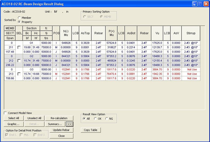
ACI318-02 RC-Beam Design Results dialog box
MEMB: Member number
SECT: Section property number
SEL: Select members for redesign and production of results
Span: Length of beam member
Section: Section Name
Bc, Hc: Width, height (depth) of beam member
bf, hf: Width, thickness of the flange of T-shape section
f'c: Design compressive strength of concrete
fy: Design yield strength of main rebars
fys: Design yield strength of shear rebars
POS: Automatic design positions (I,M,J)
The design results for M reflect the automatic design for the maximum negative and positive moments and shear forces at 1/4, 1/2 & 3/4 points.
CHK:
Status of automatic design results (Results are produced in the = "OK": Automatic design results satisfy the design strength for the factored negative moment, positive moment and shear force
= "N**": Automatic design results do not satisfy the design strength for the factored negative moment
= "*P*": Automatic design results do not satisfy the design strength for the factored positive moment
= "**V": Automatic design results do not satisfy the design strength for the factored shear force
= "NP*": Automatic design results do not satisfy the design strength for the factored negative and positive moments
= "*PV": Automatic design results do not satisfy the design strength for the factored positive moment and shear force
= "N*V": Automatic design results do not satisfy the design strength for the factored negative moment and shear force
= "NPV": Automatic design results do not satisfy the design strength for the factored negative moment, positive moment and shear force
N(-)Mu, LCB: Maximum factored negative moment occurring in the relevant member or section and the corresponding load combination.
AsTop: The area of required top rebars calculated by the program. The larger of the calculated rebar area and the minimum rebar quantity specified in the codes is presented.
Rebar(AsTop): The required number of rebars using the standard sizes specified by the user is presented.
When the reinforcing placement requires more than 2 layers, place the rebars up to the second layer. (Details...) = for 1 rebar-layer ("xx-Dyy" , "xx-#yy")
xx is the number of top rebars and yy is the standard rebar size designation
= for 2 rebar-layers ("xx-yy-Dzz" , "xx-yy-#zz")
xx is the number of upper layer top rebars, yy is the number of lower layer top rebars and zz is the standard rebar size designation.
P(+)Mu, LCB: Maximum factored positive moment occurring in the relevant member or section and the corresponding load combination.
AsBot: The area of required bottom rebars calculated by the program. The larger of the calculated rebar area and the minimum rebar quantity specified in the codes is presented.
Rebar(AsBot): The required number of rebars using the standard sizes specified by the user is presented.
When the reinforcing placement requires more than 2 layers, place the rebars up to the second layer.(Details...) = for 1 rebar-layer ("xx-Dyy" , "xx-#yy")
xx is the number of bottom rebars and yy is the standard rebar size designation.
= for 2 rebar-layers ("xx-yy-Dzz" , "xx-yy-#zz")
xx is the number of lower layer bottom rebars, yy is the number of upper layer bottom rebars and zz is the standard rebar size designation.
Vu, LCB: Maximum factored shear force occurring in the relevant member or section and the corresponding load combination.
AsV: Reinforcing steel section area (LengthUnit 2 / LengthUnit x 100 ) required for the shear force calculated by the program. The larger of the calculated rebar area and the minimum rebar quantity specified in the codes is presented.
Stirrup: The required rebar spacing based on AsV using the standard sizes for sub-rebars entered by the user.
The following are displayed for Stirrup based on the automatic design results:(Details...) = "#xx @yyy" , "Dxx @yyy"
xx is the standard rebar size designation and yyy is the rebar spacing (unit: inch).
= "Failure"
Note
Common Control
When the design results are sorted by Property, rebar data will be updated in accordance with the most unfavorable design result among all the members attributed to the relevant section property.
When the design results are sorted by Member, rebar data will be updated by individual members.
Redesign the selected members. When the redesign is executed from the results displayed by section properties, all the members attributed to the same sections are included. This option can be used even when the rebar splice data is changed.
Note When modifying the design parameters ('Modify Concrete Material', etc.) that can affect all the design results, this option cannot be used since the design results will be deleted.
Note In all the Design Result Dialogs & Code Checking Result Dialogs, the Graphic Reports can be saved in a batch.
The design results "Sorted by Member" support the detail calculations.
The maximum forces calculated at each sectional location (I,M & J) are produced when "Sorted by Property" is selected, representing all the members of same properties.
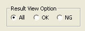
All: Produce all the auto-designed results in the Design Results dialog box
OK: From the auto-designed results, display only the design results that have met the design requirements (OK) in the Design Results dialog box
NG: From the auto-designed results, display only the design results that have not satisfied the design requirements (NG) in the Design Results dialog box
| ||||||||||||||||||||||||||||||||||||||||||||||||
|
| ||||||||||||||||||||||||||||||||||||||||||||||||
 state for convenience)


 exceeds
 (Refer to the Note below) in
 : Display the applicable
code for automatic design.
: Display the applicable
code for automatic design.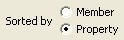
 : Display the unit system
selected by the user.
: Display the unit system
selected by the user.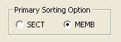
 Revision of Gen 2010
 : Update
the rebar quantity for each property or member in the rebar design data
in order to use for strength verification purposes.
: Update
the rebar quantity for each property or member in the rebar design data
in order to use for strength verification purposes.  : Select all members
 : Cancel the selection
of all members
: Cancel the selection
of all members
 : Display detail automatic
design results
: Display detail automatic
design results : Display simplified
automatic design results
: Display simplified
automatic design results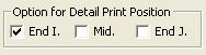 : Select the sectional
location data to be included in the output.
: Select the sectional
location data to be included in the output. : Produce the automatic
design results in summary calculations for the selected members.
: Produce the automatic
design results in summary calculations for the selected members.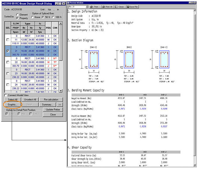
 : Produce the automatic
design results in detail calculations for the selected members.
: Produce the automatic
design results in detail calculations for the selected members.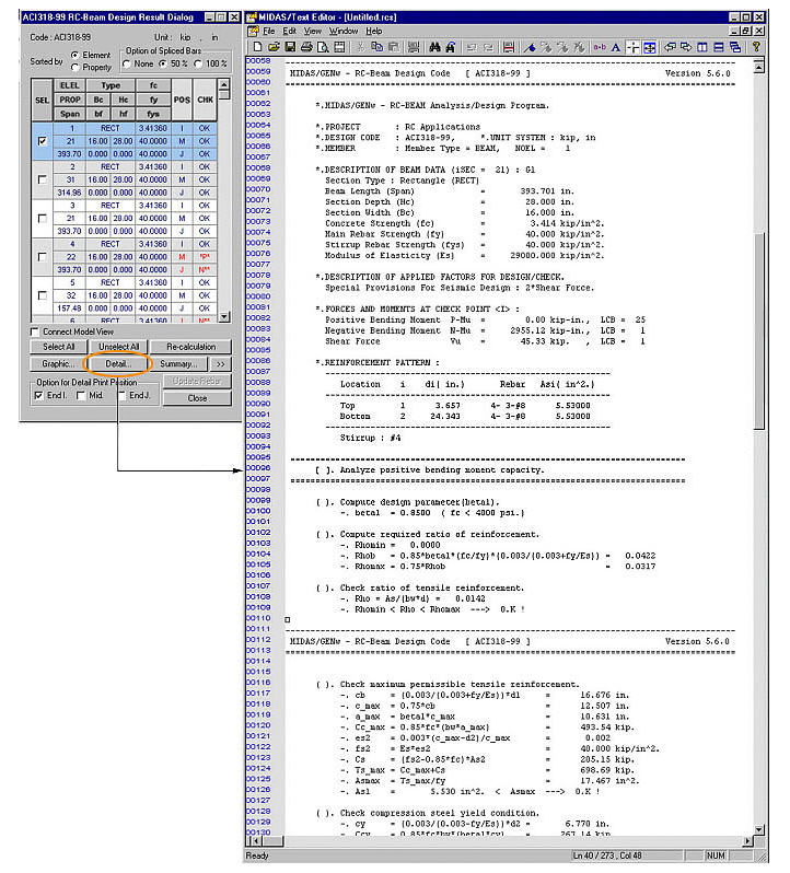
 : Produce the summary
list of automatic design results for the selected members.
: Produce the summary
list of automatic design results for the selected members.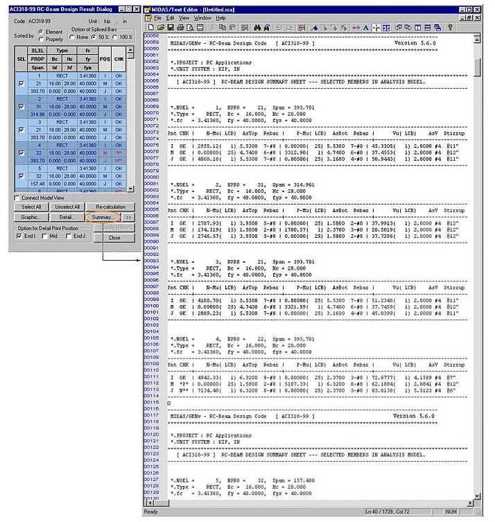
 : Check in the option
to select and highlight the selected members in Model View.
: Check in the option
to select and highlight the selected members in Model View. : Close the dialog box.