Wall Design
| |||||||||||||||||||||||||||||||||||||||||||||
|
| |||||||||||||||||||||||||||||||||||||||||||||
|
| |||||||||||||||||||||||||||||||||||||||||||||
|
Using the results obtained from the analysis of the entire structure and additional design data, automatically design concrete wall members according to the following design codes: American Concrete Institute (ACI318-89, ACI318-95, ACI318-99, ACI318-02 & ACI318-05), Canadian Standards Association(CSA-A23.3-94), British Standard (BS8110-97) and European Standard (ENV 1992-1-1:1992 & EN 1992-1-1:2004).
Architectural Institute of Japan (AIJ-WSD99), Architectural Institute of Korea (AIK-USD94), Korean Society of Civil Engineers (KSCE-USD96), Korean Concrete Institute ((KCI-USD03 &KCI-USD99), Architectural Institute of Korea (AIK-WSD2K), China Standard((GB50010-02),Taiwan Standard (TWN-USD92) and Indian Standard (IS456:2000) are available upon request. | |||||||||||||||||||||||||||||||||||||||||||||
|
| |||||||||||||||||||||||||||||||||||||||||||||
|
| |||||||||||||||||||||||||||||||||||||||||||||
|
| |||||||||||||||||||||||||||||||||||||||||||||
|
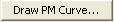
From the Main Menu select Design > Concrete Code Design > Wall Design.
Shortcut key : [Ctrl]+4 | |||||||||||||||||||||||||||||||||||||||||||||
|
| |||||||||||||||||||||||||||||||||||||||||||||
|
| |||||||||||||||||||||||||||||||||||||||||||||
|
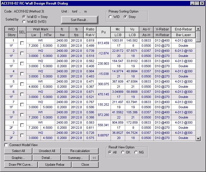
The automatic design results "sorted by Wall ID+Story" are based on the maximum axial forces, biaxial moments and shear forces calculated at the element locations, I & J, in accordance with the load combinations for concrete design. Factored strength ratios with respect to the design strengths are evaluated on the basis of P-M interaction diagrams.
The automatic design results "sorted by Wall ID" are based on the maximum vertical rebar ratios extracted from the P-M diagrams considering Wall ID+Story for each element, sectional locations and the load combinations for concrete design. The results appear in blue when the automatic design for the given lengths and thicknesses are satisfactory, otherwise they appear in red which represent the results are unsatisfactory.
The automatic design results are produced in the unit system selected by the user.
The automatic design provides optimal rebar sizes and spacings satisfying the rebar (vertical, horizontal) spacing and the rebar ratios. The user may enter the rebar information (vert. reinf. -max. 5 types, end rebar size, horizontal rebar size).
When the user elects not to enter the rebar data, the program automatic ally uses #4 for the vertical rebars, #3 for end rebars and #3 for horizontal rebars.
ACI318-02 RC-Wall Design Results Dialog Box
Wall ID+Story: Wall number and story
WID: Wall number entered by the user
Story: Story name defined in the structural analysis model
SEL: Select members for redesign and production of results
Wall Mark: Designation for shear wall member
Lw: Length of shear wall member
HTw: Story height of shear wall member
hw: Thickness of shear wall member
f'c: Design compressive strength of concrete
fy: Design yield strength of vertical rebars
fys: Design yield strength of horizontal rebars
CHK:
Status of automatic design results (Results are produced in the
= "OK": Automatic design results satisfy the design strength for the factored axial force, moment and shear force
= "P**": Automatic design results do not satisfy the design axial strength for the factored axial force
= "*M*": Automatic design results do not satisfy the design strength for the factored moment
= "**V": Automatic design results do not satisfy the design strength for the factored shear force
= "PM*": Automatic design results do not satisfy the design strength for the factored axial force and moment
= "*MV": Automatic design results do not satisfy the design strength for the factored moment and shear force
= "P*V": Automatic design results do not satisfy the design strength for the factored axial force and shear force
= "PMV": Automatic design results do not satisfy the design strength for the factored axial force, moment and shear force
Pu: Factored compression (tension) force acting on the shear wall member under the load combination displayed in LCB (Mu)
= Pu > 0: Compressive axial force acting in the member's axial direction
= Pu < 0: Tensile axial force acting in the member's axial direction
Mc, LCB: Factored bending moment and the corresponding load combination that produces the maximum rebar ratio in the P-M interaction diagram.
As-V: Vertical rebar quantity (LengthUnit 2 / LengthUnit x 100 ) calculated by the program. The larger of the calculated rebar area and the minimum rebar quantity specified in the codes is presented. The end rebars are separately identified by number and spacing and excluded from AsV.
Note
V-Rebar: Optimum placement of vertical rebars, AsV, using the rebar sizes entered by the user.
The following are displayed for V-Rebar based on the automatic design results :
= #xx @yyy", "Dxx @yyy"
xx is the designated standard rebar size, yyy is the rebar spacing (unit: inch).
= "Not Use"
Rebar sizes satisfying the minimum rebar spacing specified in the codes do not exist.
Vu, LCB: Maximum factored shear force occurring in the relevant wall element and the corresponding load combination.
As-H: Reinforcing steel section area (LengthUnit 2 / LengthUnit x 100 ) required for the horizontal shear force calculated by the program. The larger of the calculated rebar area and the minimum rebar quantity specified in the codes is presented.
Note
H-Rebar: The required rebar spacing based on AsH using the standard size for horizontal rebars entered by the user.
The following are displayed for H-Rebar based on the automatic design results :
= #xx @yyy, "Dxx @yyy"
xx is the standard rebar size designation and yyy is the rebar spacing (unit: inch).
= "Failure"
Note
End-Rebar: Optimal placing of end-rebars automatically calculated using the rebar diameter equal to or larger than the rebar size entered by the user.
The following are displayed in End-Rebar based on the automatic design results.
= "nn-Dxx@yyy", "nn-#xx@yyy"
nn is the number of end rebars, xx is the standard rebar size and yyy is the rebar spacing (unit: mm).
= "Not Use"
The minimum rebar spacing specified in the codes can not be satisfied or the wall member length is insufficient to reinforce.
Bar Layer: Number of layers for vertical rebars. Only 2 layers are used.
Common Control
Display the applicable code and design method (selected among Method1, Method2, Method3 & Method4) for automatic design.
"Sorted by Wall ID+Story" displays the design results including the maximum vertical rebar ratios obtained from the P-M interaction diagrams and factored shear forces at the positions (I&J) based on all the load combinations.
"Sorted by Wall ID" displays the design results of the maximum vertical rebar ratios obtained from the P-M interaction diagrams and factored shear forces by examining all the shear wall members attributed to the relevant lengths and thicknesses. Since the results do not pertain to a single element, "Wall ID+Story" is "0".
Once Wall ID is selected, SEL controls every "Wall ID+Story" pertaining to the same "Wall ID".
The updated rebar data are used for strength verification.
Redesign the selected members. When the redesign is executed from the results displayed by section properties, all the members attributed to the same sections are included. This option can be used even when the rebar splice data is changed.
Note When modifying design parameters ('Modify Concrete Material', etc.) that can affect all the design results, this option cannot be used since the design results will be deleted.
The design results "Sorted by Wall ID+Story" support the detail calculations.
"Sorted by Wall ID" produces the results pertaining to the maximum vertical reinforcing, representing all the walls of same ID's.
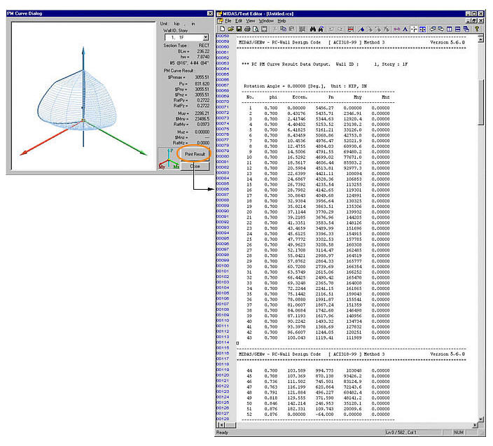
Plot the results and the corresponding P-M interaction diagram applicable for the factored axial force and biaxial moments.
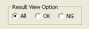
All: Produce all the auto-designed results in the Design Results dialog box
OK: From the auto-designed results, display only the design results that have met the design requirements (OK) in the Design Results dialog box
NG: From the auto-designed results, display only the design results that have not satisfied the design requirements (NG) in the Design Results dialog box
Sorting output results
Select the sorting reference.
Select a unit system for output.
List for Selecting List the names of wall members to be selected
List for Printing List the names of the selected wall members
Select the story sorting sequence (ascending or descending)
SEL: Select the stories for which the results are to be produced
Story: Assigned floors
Produce the summary list of the design results for the selected members. Produce the maximum values for each Wall Mark or Wall ID at the selected story.
Produce the required reinforcing quantity for each Wall Mark or Wall ID at the selected story.
| |||||||||||||||||||||||||||||||||||||||||||||
|
| |||||||||||||||||||||||||||||||||||||||||||||
 state for convenience)
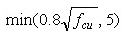


 exceeds
 (Refer to the Note below) in

 : Display the unit system
selected by the user.
: Display the unit system
selected by the user. :Update the rebar quantity
for each "Wall ID+Story" in the rebar design data.
:Update the rebar quantity
for each "Wall ID+Story" in the rebar design data. : Select all members
 : Cancel the selection
of all members
: Cancel the selection
of all members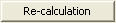
 : Display detail automatic
design results
: Display detail automatic
design results : Display simplified
automatic design results
: Display simplified
automatic design results : Produce the automatic
design results in summary calculations for the selected members.
: Produce the automatic
design results in summary calculations for the selected members.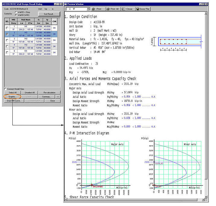
 : Produce the automatic
design results in detail calculations for the selected members.
: Produce the automatic
design results in detail calculations for the selected members.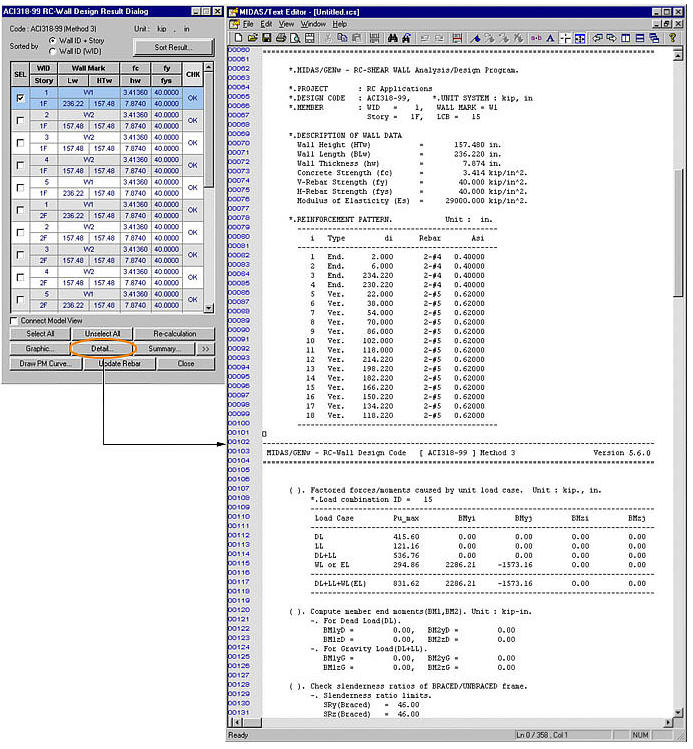
 : Produce the summary
list of automatic design results for the selected members.
: Produce the summary
list of automatic design results for the selected members.
 : Check in the option
to select and highlight the selected members in Model View.
: Check in the option
to select and highlight the selected members in Model View. : Close the dialog box
 : Sort design results
by Wall Marks and the stories of Wall ID
: Sort design results
by Wall Marks and the stories of Wall ID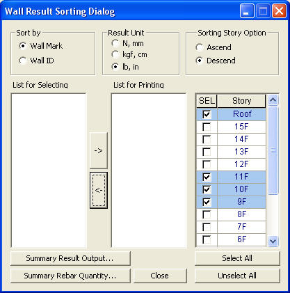
 : Send the selected
Wall ID or Wall Mark from List for Selecting to List for Printing
: Send the selected
Wall ID or Wall Mark from List for Selecting to List for Printing : Remove the selected
Wall ID or Wall Mark from List for Printing
: Remove the selected
Wall ID or Wall Mark from List for Printing