Brace Checking
|
|
|
|
|
|
Using the results obtained from the analysis of the entire structure and additional design data, automatically design concrete beam members according to the following design codes: American Concrete Institute (ACI318-89, ACI318-95, ACI318-99, ACI318-02 & ACI318-05), Canadian Standards Association(CSA-A23.3-94), British Standard (BS8110-97) and European Standard (ENV 1992-1-1:1992 & EN 1992-1-1:2004).
Architectural Institute of Japan (AIJ-WSD91), Architectural Institute of Korea (AIK-USD94), Korean Society of Civil Engineers (KSCE-USD96), Korean Concrete Institute (KCI-USD99) and Architectural Institute of Korea (AIK-WSD2K) are available upon request. |
|
|
|
|
|
|
|
From the Main Menu select Design > Concrete Code Check > Brace Checking.
Shortcut key : [Ctrl]+7 |
|
|
|
|
|
The strength verification results sorted by elements are based on the maximum axial forces, biaxial moments and shear forces, which result in the maximum strength ratios calculated at the positions (I, 1/4, 1/2, 3/4 & J) of each element in accordance with the load combinations for concrete design. The maximum strength ratios with respect to the design strengths are evaluated on the basis of P-M interaction diagrams.
The strength verification results sorted by section properties are based on the results that produce the maximum strength ratios in the P-M diagrams by considering all the elements and locations pertaining to each section in accordance with the load combinations for concrete design.
The results appear in blue when the strength verifications for the given section properties and rebars are satisfactory, otherwise they appear in red which represent the results are unsatisfactory.
Strength verification can be performed by automatic design or by using the information on main rebars (diameter, number), sub-rebars (diameter, number) and design parameters entered by the user.
Strengths cannot be verified without the rebar data.
The strength verification results are produced in the unit system selected by the user.
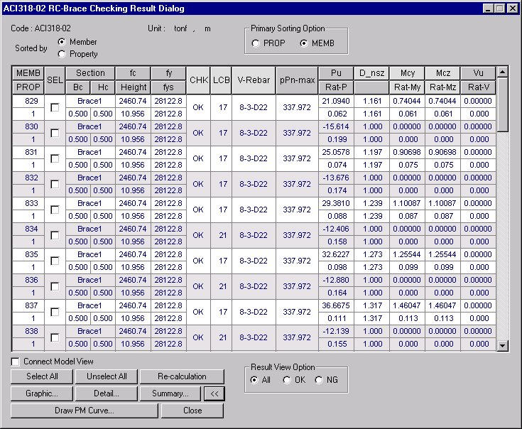
ACI318-02 RC-Brace Checking Results dialog box
MEMB : Member number
PROP: Section property number
SEL: Select members for strength verifications and production of results
Section : Section name
Bc, Hc: Width, height (depth) of brace member
Height: Height (length) of brace member
f'c: Design compressive strength of concrete
fy: Design yield strength of main rebars
fys: Design yield strength of shear rebars
CHK: Status of strength verification results
= "OK": Strength verification results satisfy the design strength for the factored axial force, moment and shear force
= "P**": Strength verification results do not satisfy the design strength for the factored axial force
= "*M*": Strength verification results do not satisfy the design strength for the factored moment
= "**V": Strength verification results do not satisfy the design strength for the factored shear force
= "PM*": Strength verification results do not satisfy the design strength for the factored axial force and moment
= "*MV": Strength verification results do not satisfy the design strength for the factored moment and shear force
= "P*V": Strength verification results do not satisfy the design strength for the factored axial force and shear force
= "PMV": Strength verification results do not satisfy the design strength for the factored axial force, moment and shear force
LCB: Load combination yielding the maximum factored load ratio determined from the P-M diagram. The program examines all the load combinations and sectional locations of the relevant element or section property to find the maximum ratio.
V-Rebar:
Standard rebar size and the number of main rebars entered by the user
or updated by automatic design.
Notation: n1 - n2 - #xx(Dxx)
(n1: number of main rebars, n2: number of rows of main rebars, #xx(Dxx): standard size for main rebars)
phiPnmax: Maximum design compressive strength for the shear wall member
Pu: Factored compression (tension) force acting on the brace member under the load combination displayed in LCB
= Pu > 0: Compressive axial force acting in the member's axial direction
= Pu < 0: Tensile axial force acting in the member's axial direction
Rat-P: Ratio of the factored axial force to the design axial strength. The ratio larger than 1.0 signifies that the design strength is unsatisfactory based on the given rebars and section of the relevant brace member.
D_nsy: Moment magnification factor for a brace braced against sideway, either auto-calculated in the program or entered by the user, to reflect the effects of member curvature between the ends of the brace. The factor applies to the moment about the element's local y-axis of a brace.
D_nsz: Moment magnification factor for a brace braced against sideway, either auto-calculated in the program or entered by the user, to reflect the effects of member curvature between the ends of the brace. The factor applies to the moment about the element's local z-axis of a brace.
Mcy: Amplified bending moment about the element's local y-axis
Mcz: Amplified bending moment about the element's local z-axis
RatMy: Ratio of the factored bending moment to the design bending moment strength about the strong axis. The ratio larger than 1.0 signifies that the design strength is unsatisfactory based on the given rebars and section of the relevant brace member.
RatMz: Ratio of the factored bending moment to the design bending moment strength about the weak axis. The ratio larger than 1.0 signifies that the design strength is unsatisfactory based on the given rebars and section of the relevant brace member.
Vu: Maximum factored shear force of the relevant element or section on the basis of examining all the load combinations at the 5 sectional locations.
Rat-V: Ratio of the factored shear force to the design shear strength
Common Control
"Sorted by Element" displays the strength verification results of the maximum strength ratios obtained from the P-M interaction diagrams and factored shear forces extracted from all the load combinations at the sectional locations (I, 1/4, 1/2, 3/4 & J).
"Sorted by Property" displays the strength verification results of the maximum strength ratios obtained from the P-M interaction diagrams and factored shear forces representing all the elements attributed to the relevant section property.
Since the results do not pertain to a single element, ELEM (element number) is "0".
Once property is selected, SEL controls all the elements attributed to the same section properties.
Re-verify the strengths of the selected members. When strength re-verification is executed from the results displayed by section properties all the elements attributed to the same sections are included.
The strength verification results "Sorted by Element" support the detail calculations.
"Sorted by Property" produces the results of the maximum quantity of rebars representing all the members of same properties.
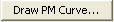
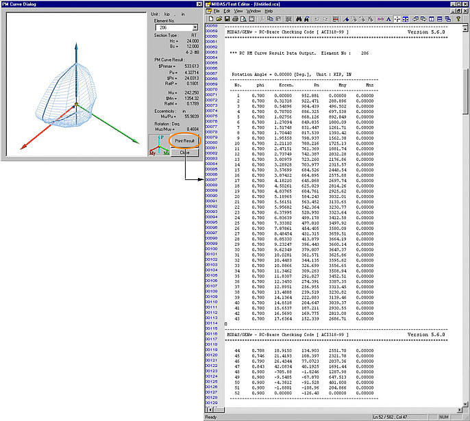
Plot the results and the corresponding P-M interaction diagram applicable for the factored axial force and biaxial moments.
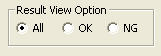
= All: Produce all the strength-verified results in the Checking Results dialog box
= OK: From the strength-verified results, display only the results that have met the design requirements (OK) in the Checking Results dialog box
= NG: From the strength-verified results, display only the results that have not satisfied the design requirements (NG) in the Checking Results dialog box
|
|
|
 in the
  : Display the applicable
code for strength verification.
: Display the applicable
code for strength verification.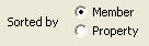
 : Display the unit system
selected by the user.
: Display the unit system
selected by the user. : Select all members
 : Cancel the selection
of all members
: Cancel the selection
of all members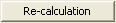
 : Display detail strength
verification results
: Display detail strength
verification results : Display simplified
strength verification results
: Display simplified
strength verification results : Produce the strength
verification results in summary calculations for the selected members.
: Produce the strength
verification results in summary calculations for the selected members.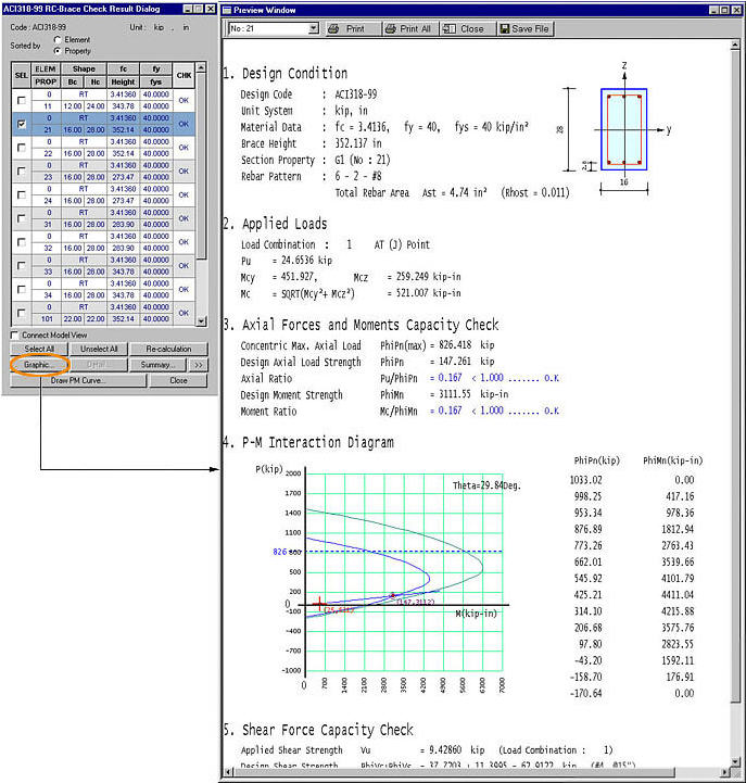
 : Produce the strength
verification results in detail calculations for the selected members.
: Produce the strength
verification results in detail calculations for the selected members.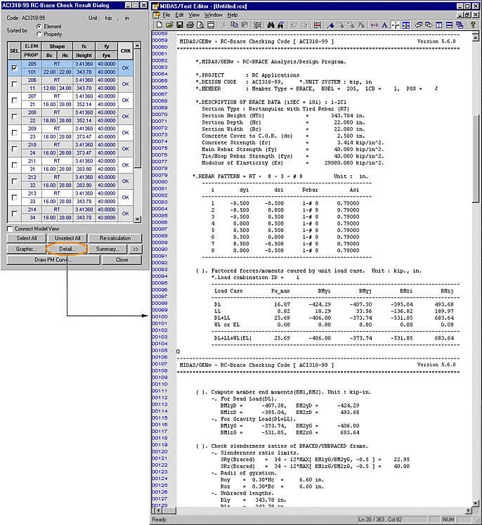
 : Produce the summary
list of strength verification results for the selected members.
: Produce the summary
list of strength verification results for the selected members.
 : Check in the option
to select and highlight the selected members in Model View.
: Check in the option
to select and highlight the selected members in Model View. : Close the dialog box