Enter the necessary analysis conditions to be applied to Pushover analysis.
The Followings can be controlled.
1.
Initial Load: Enter the initial
load (in general, the gravity loads) for pushover analysis.
2. Convergence
Criteria: Specify the maximum number of (iterations) sub-iterations
and a tolerance limit for convergence criterion.
3. Stiffness
Reduction Ratio: Specify stiffness reduction ratios after the 1st
and 2nd yielding points (1st yielding for bilinear curve, 1st and 2nd
yielding for trilinear curve) relative to the elastic stiffness.
4. Reference
location for distributed hinges: Specify the reference location
for calculating yield strength of beam elements which distributed hinge
is assigned.
From the Main
Menu selectDesign > Pushover Analysis
> Pushover Global Control.
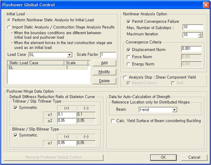
Pushover
Global Control dialog box
Revision of Gen 2011
[Initial
Load]
Define,
modify or delete the initial load cases, which will be applied prior to
pushover analysis.
Perform Nonlinear Static Analysis for Initial Load
This is the general way of applying the initial load.
Import Static Analysis / Construction Stage Analysis
Results
1. When the boundary conditions are different between the initial load
and the pushover load.
2. To use the result from the final construction stage as the initial
load.
Note 1
When using the result from the final construction
stage as the initial load for the pushover analysis, the member forces
from the construction stage analysis will be imported and nonlinear analysis
will not be performed for the initial load.
Note 2
For the following cases, nonlinear analysis
will not be performed for the initial load but the result from the static
analysis will be imported for the pushover analysis.
-
When the boundary conditions/section stiffness scale factors are different
between the initial load and the pushover load
-
When using the member forces from the final construction stage as the
initial load for the pushover analysis Type your drop-down text here.
Load Case
Select the load cases, which are to be defined
as the initial load for pushover analysis, among the load cases applied
to static analysis.
Scale Factor
Enter the magnification/reduction factors
to be applied to each selected load case for the initial load.
Note 1
If the following temperature
loads are entered as an Initial Load, pushover analysis cannot be performed.
1. Beam Section Temperature
2. Temperature Gradient
3. System Temperature
4. Nodal Temperature
5. Element Temperature
Note 2
The member
forces caused by the initial load (in general, the gravity load) are added
to the resulting member forces due to pushover analysis. However, the
displacements caused by the initial load are not considered in the pushover
analysis.
Note 3
If P-M interaction is considered
in the hinge properties, it is recommended to apply the initial load.
Note 4
In order to
check the results due to initial load in the pushover analysis, a linear
static analysis for the load cases which are defined as initial load should
be performed.
Revision of Gen 2010
[Analysis Stop : Shear
Component Yield]
Specify the
condition of termination for the Pushover analysis.
Analysis Stop
: Shear Component Yield
Beam/Column:
Select this option to automatically terminate pushover analysis if a shear
hinge in a beam or a column member occurs.
Wall:
Select this option to automatically terminate pushover analysis if a shear
hinge in a wall occurs.
Note
If the analysis is automatically
terminated due to yielding of shear hinge, analysis results can be examined
up to the last pushover step.
[Nonlinear Analysis Option]
Specify the maximum number of sub-iterations
and a tolerance limit for convergence criterion.
Permit Convergency Failure
By increasing the number of steps in an iterative
nonlinear analysis, the rate of convergence can be improved. However if
the number of steps is large, the analysis could be very time-consuming.
When this option is checked on and if the
analysis results do not converge, midas automatically subdivides the step
at which divergence occurs. Therefore analysis can be converged without
increasing the number of steps. When this option is checked off and if
the analysis results do not converge, the analysis will be terminated.
Max. Number of Sub-steps
It is maximum number of Sub-steps, which
are segmented from each increment step
Maximum Iteration
Enter the maximum number of sub-iterations
in an increment step for repetitive analyses to satisfy an equilibrium
condition of the structure.
Note 1
Specified number of sub-iterations
is applied to all the pushover load cases.
The difference between internal and external loads
acting on the structure is called unbalanced force. In
pushover analysis the equilibrium is achieved by reducing the unbalanced
force through an iterative solver such as Newton-Raphson method.
Procedure
of Newton-Raphon method
1.
When the iteration is performed:
The iterative procedure is continued until
the unbalanced force becomes less than or equal to the specified tolerance
and as a result, convergence criterion is satisfied.
2.
When the iteration is not performed (when the maximum number of iterations
is entered as 1):
The unbalanced force is added to the external
load in the subsequent step.
Convergence Criteria
Specify a tolerance limit for convergence.
If the incremental error falls within the tolerance, the iteration stops
within the corresponding analysis step prior to reaching the maximum number
of iterations and subsequent steps ensue.
Note
1
Convergence
Condition
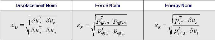
There are
three convergence criteria (displacement norm, force norm and energy norm)
to check the convergence for an iterative process. The user can select
more than one norm to be reflected in the iteration process.
Where, : Displacement norm
: Force norm
: Energy norm
: Effective load vector in
the nth iteration step
: Incremental displacement
vector in the nth iteration step
: Accumulated Incremental
displacement vector after n iterations
Note
2
In general,
applying displacement norm is enough. In a very special case, an exact
solution is not obtained because of remaining unbalanced force is not
negligible although they converge by the displacement norm. In that case,
the user may solve the problem by considering additional criteria (force
norm and energy norm)
Note
3
When multiple norms are
applied, the number of iterations in each increment step increases.
Note
4
When the convergence
tolerance is not satisfied, the remaining unbalanced force is added to
the external load in the subsequent step. Therefore, if the analysis results
are converged in the current step, the failure of convergence in the previous
step does not affect analysis results.
[Pushover Hinge Data Option]
Define the default stiffness reduction ratio
of the skeleton curve. Also specify the reference location for calculating
yield strength of beam element when the pushover hinge property is defined
as distributed type.
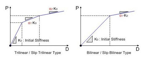
Default Stiffness Reduction Ratio of Skeleton Curve
Specify
the stiffness reduction ratios after the 1st and 2nd yielding points (1st
yielding for bilinear curve, 1st and 2nd yielding for trilinear curve)
relative to the elastic stiffness when the skeleton curve is Bilinear,
Slip Bilinear, Trilinear type or Slip Trilinear type.
Trilinear
/ Slip Trilinear Type :Specify the stiffness reduction ratios after
the 1st and 2nd yielding points for Trilinear curve.
α1:Stiffness
reduction ratio after the 1st yielding point (α1 ≤ 1.0)
α2:Stiffness
reduction ratio after the 2nd yielding point(α2
≤ α1 ≤ 1.0)
Bilinear / Slip Bilinear
Type : Specify the stiffness reduction
ratios after yielding point for Bilinear curve.
α1:Stiffness
reduction ratio after yielding point (α1 ≤ 1.0)
Note
If the user
changes the value of 'Default Stiffness Reduction Ratio of Skeleton Curve'
and click [OK] button, Stiffness Reduction Ratio is selected as 'Use Value
of Global Control Data' option in the Directional Properties of Pushover
Hinge dialog.
Data
for Auto-Calculation of Capacity
Reference
Location only for Distributed Hinges
Specify the reference location (i-end, j-end,
center) for calculating yield strength of beam element when the pushover
hinge property is defined as distributed type.
Reference
Design Code (Eurocode 8: 2004)
Specify
scale factors for ultimate rotation and identify secondary seismic elements.
(Eurocode 8 only)
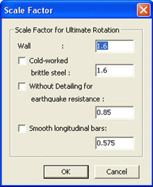
Scale Factor
for Ultimate Rotation : When calculating the total chord rotation
capacity at ultimate of concrete members, following conditions can be
considered as per A.3.1.1, ANNEX A, Eurocode 8-3.
Cold-worked
brittle steel
Without
detailing for earthquake resistance
Smooth
longitudinal bars
Secondary
Seismic Elements: Identify secondary seismic elements, if any,
by selecting predefined Structure Group.
 Revision of Gen 2011
 Perform Nonlinear Static Analysis for Initial Load
 Analysis Stop
: Shear Component Yield
Analysis Stop
: Shear Component Yield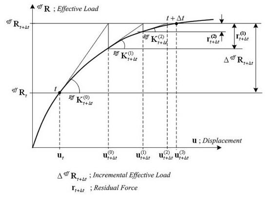
 : Displacement norm
 : Force norm
 : Effective load vector in
the nth iteration step
: Effective load vector in
the nth iteration step : Incremental displacement
vector in the nth iteration step
: Incremental displacement
vector in the nth iteration step  :
: