Pushover Load Case


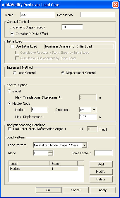
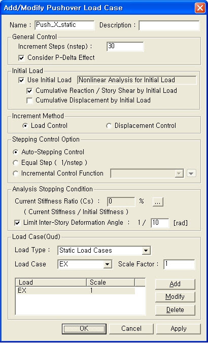
Enter, modify or delete load cases and analysis conditions for pushover analysis.


From the Main Menu select Design > Pushover Analysis > Pushover Load Cases.


Click the to create new load cases. Click the to confirm or modify and the to delete the data entry.
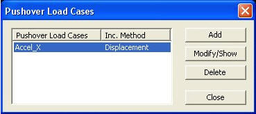


Pushover Load Cases dialog box


  •  If Load Control is selected

    If Load Control is selected, pushover analysis is carried out to reach the estimated collapse load (Qud) through the load increments. 


    Pushover Load Case dialog box (Load Control)


    Load Case Name


    Enter the load case name pertaining to Pushover analysis.


    Description


    State a brief description related to the pushover load case.


    General Control


    Incremental Steps (nstep) : Number of steps to reach the estimated collapse load


    Note

    The incremental steps must be entered as a positive integer value (nstep¡Ã1), and minimum 20 steps are recommended. (Default = 20)


    Consider P-Delta Effect : Check on to consider P-Delta geometric nonlinear effects.


    Note 1

    P-Delta effect is very important in pushover analysis. Lateral displacement caused by the lateral load can be magnified by the gravitational load and this effect can reduce the lateral stiffness of the structure. Especially when plastic hinges occur at the lower part of the columns, which are under large axial forces, the reduced lateral stiffness can cause the collapse of the structure.


    Note 2

    Tthe stiffness rapidly decreases after reaching peak strength in case of FEMA and Eurocode type hinge, while geometric stiffness is neglected after reaching ultimate strength, i.e. Collapse Prevention (CP) and Near Collapse (NC), respectively.


    Revision of Gen 2011


    Initial Load


    Accumulate the reaction/story shear/displacement due to the initial load to the pushover analysis result.


    Use Initial Load


    Reaction / Story Shear by Initial Load : Accumulate the reaction/story shear due to the initial load


    Displacement by Initial Load : Accumulate the displacement due to the initial load


    Note 1

    When P-M interaction is considered, the user needs to apply the initial load.


    Note 2

    When importing the static analysis result (ST) and the construction stage analysis result (CS), reaction and displacement are not cumulated.


    Stepping Control Option


    Specify the control data for the load increment.


    Auto-Stepping Control : The applied load (Qud) is divided by the automatically calculated load parameters. The first step is loaded up to 90% of the elastic limit of the structure. Further steps are automatically divided by the ratio of.


    Note 1

    Elastic limit means the estimated load under which the first yield occurs.


    Note 2Analysis method and example for the Auto-Stepping Control option


     Example


    Equal Step (1/n step) :The applied load (Qud) is equally divided by the number of nstep.

    Incremental Control Function : The applied load (Qud) is divided by the user-defined function. Refer to “Design>Pushover Analysis>Pushover Increment Functions” to see how to define user-defined function.


    Analysis Stopping Condition


    Specify the condition of termination of Pushover analysis.


    Current Stiffness Ratio (Cs) : If the Current Stiffness Ratio (Cs) is entered and the ratio of the stiffness at the current an incremental step to the initial stiffness reaches the specified value, the analysis is terminated. For example, if the user specifies the Current Stiffness Ratio as 5%, analysis will be terminated when the ratio of the current stiffness to the initial stiffness becomes 0.05.  


    Note

    In addition to the above conditions for termination of analysis, analysis is also terminated if the maximum number of increments is reached, or negative values are encountered in the stiffness matrix.


    Limit Inter-Story Deformation Angle : If the Limit Inter-Story Deformation Angle is entered and the maximum Inter-Story Deformation Angle reaches the specified value, the analysis is terminated. (Default=1/10)


    Load Case(Qud)


    Define the type of load pattern (ratio of magnitude) to be applied to pushover analysis


    Load Type


    Static Load Case: Use the load pattern of static load cases that have been defined.


    Note

    The combination of load cases multiplied by the corresponding scale factors is used as the load pattern.


    Uniform Acceleration: The load is distributed relative to the inertia forces developed in the structure, which has been subject to a uniform acceleration. If the acceleration is uniform, the load pattern is determined proportionally to the mass at each story level.


    Revision of Gen 2011


    Note.Calculation of Transformation Factor in EC8/Masonry and NTC 2008 for Load pattern Uniform Acceleration

    The value of gamma obtained for EC8/Masonry and NTC 2008 will always be 1.

    Gamma is defined as:


    Since the mode shape is such that the displacement of all the stories is assumed to be 1. Hence whatever be the weight of the story the gamma will always be 1.


    Assumed Mode Shape for Uniform Acceleration


    Mode Shape:The pushover load pattern retains a mode shape and as such, eigenvalue analysis is a prerequisite. The user can select the orders of natural modes that are applied to determining the pushover load pattern.


    Revision of Gen 2011


    Normalized Mode Shape* Mass: The Load pattern for the pushover analysis is obtained by the normalized mode shape*mass.


                                    Normalization of Mode Shape 


    Note 1. Choice of Master Node

    It is recommended that the master node be the node at the centre of mass of the structure so that the normalized mode shape is such that the normalized value of phi for centre of mass at roof becomes 1.


    Note 2. Generation of Lateral Load Pattern of "Mode Shape*Mass"

    The following is an example of how the lateral load pattern is obtained:


    Revision of Gen 2011


    Note. Calculation of Transformation Factor in EC8/Masonry and NTC2008for Load Case Normalized Mode Shape * Massand Mode Shape


    Gamma can be calculated in the following two ways:

    1. Based on 2D Behaviour (EC8-1:2004 Annex B)

    2. Based on 3D Behaviour


    1. Based on 2D Behaviour (EC8-1:2004 Annex B):

    2D Behavior is based on EC8 -1 :2004 Annex B and determines the value of gamma by  only considering the direction in which pushover analysis is performed .

    Hence the value of gamma is :


    2. Based on 3D Behaviour: 3D Behavior determines the gamma  by considering lateral deflection in all the possible directions.

    Hence the value of gamma becomes:


    Load Case/Direction/Mode: Specify the load cases/directions/mode related to the specified load type.


    Note 1

    For the Static Load Cases: All the static load cases are activated.  

    For the Uniform Acceleration: Load distribution directions (DX, DY, DZ) are activated.

    For the Mode Shape and Mode Shape * Mass: The User directly enters the mode. For this option, eigenvalue analysis must precede pushover analysis. 


    Note 2

    If the following temperature loads are entered in the Load Pattern input box, pushover analysis cannot be performed.

    1. Beam Section Temperature

    2. Temperature Gradient

    3. System Temperature

    4. Nodal Temperature

    5. Element Temperature


  •  If Displacement Control is selected


    If Displacement Control is selected, pushover analysis is carried out to reach the target displacement through the incremental displacements.


    Pushover Load Case dialog box (Displacement Control)


    Load Case Name


    Enter the load case name pertaining to Pushover analysis.


    Description


    State a brief description related to the pushover load case.


    General Control


    Specify the general control data for nonlinear analysis.


    Incremental Steps (nstep) : Number of steps to reach the prescribed displacement


    Note

    The incremental steps must be entered as a positive integer value (nstep¡Ã1), and minimum 20 steps are recommended. (Default = 20)


    Use Initial Load : Check on to assign the load defined prior to Pushover analysis as the initial load for Pushover analysis.


    Consider P-Delta Effect : Check on to consider P-Delta geometric nonlinear effects.


    Note 1

    P-Delta effect is very important in pushover analysis. Lateral displacement caused by the lateral load can be magnified by the gravitational load and this effect can reduce the lateral stiffness of the structure. Especially when plastic hinges occur at the lower part of the columns, which are under large axial forces, the reduced lateral stiffness can cause the collapse of the structure.


    Note 2

    The stiffness rapidly decreases after reaching peak strength in case of FEMA and Eurocode type hinge, while geometric stiffness is neglected after reaching ultimate strength, i.e. Collapse Prevention (CP) and Near Collapse (NC), respectively.


    Revision of Gen 2011


    Initial Load


    Accumulate the reaction/story shear/displacement due to the initial load to the pushover analysis result.


    Use Initial Load


    Reaction / Story Shear by Initial Load : Accumulate the reaction/story shear due to the initial load


    Displacement by Initial Load : Accumulate the displacement due to the initial load


    Note 1

    When P-M interaction is considered, the user needs to apply the initial load.


    Note 2

    When importing the static analysis result (ST) and the construction stage analysis result (CS), reaction and displacement are not cumulated.


    Control Option


    Specify the Target Displacement to be applied to pushover analysis


    Global Control

    Target displacement is specified with respect to the node where the maximum translational displacement occurs.  


    Maximum Translational Displacement: Specify the max. target translational displacement.


    Note

    For any structure with an irregular plan the node and direction of maximum displacement can be changed at each increment.  


    Master Node Control

    Target displacement is specified relative to the master node.


    Master Node: Master Node number


    Master Direction: Select one of the three translational directions for the target displacement in the GCS.


    Maximum Displacement: Max. target displacement


    Analysis Stopping Condition


    Specify the condition of termination of Pushover analysis.


    Limit Inter-Story Deformation Angle : If the Limit Inter-Story Deformation Angle is entered and the maximum Inter-Story Deformation Angle reaches the specified value, the analysis is terminated. (Default=1/10)


    Load Pattern


    Define the type of load pattern (ratio of magnitude) to be applied to pushover analysis


    Load : In a pushover analysis by displacement control, relative proportions are of importance for the distribution pattern rather than the magnitudes of the loads.


    Static Load Case : Use the load pattern of static load cases that have been defined.


    Note

    The combination of load cases multiplied by the corresponding scale factors is used as the load pattern.


    Uniform Acceleration : he load is distributed relative to the inertia forces developed in the structure, which has been subject to a uniform acceleration. If the acceleration is uniform, the load pattern is determined proportionally to the mass at each story level.


    Revision of Gen 2011


    Note. Calculation of Transformation Factor in EC8/Masonry and NTC2008for Load Case Uniform Acceleration

    The value of gamma obtained for EC8/Masonry and NTC 2008 will always be 1.

    Gamma is defined as:


    Since the mode shape is such that the displacement of all the stories is assumed to be 1. Hence whatever be the weight of the story the gamma will always be 1.


    Assumed Mode Shape for Uniform Acceleration


    Mode Shape:The pushover load pattern retains a mode shape and as such, eigenvalue analysis is a prerequisite. The user can select the orders of natural modes that are applied to determining the pushover load pattern.


    Revision of Gen 2011


    Normalized Mode Shape* Mass: The Load pattern for the pushover analysis is obtained by the normalized mode shape*mass.


                                    Normalization of Mode Shape 


    Note 1. Choice of Master Node

    It is recommended that the master node be the node at the centre of mass of the structure so that the normalized mode shape is such that the normalized value of phi for centre of mass at roof becomes 1.


    Note 2.Generation of Lateral Load Pattern for "Mode Shape*Mass"

    The following is an example of how the lateral load pattern is obtained:

    Revision of Gen 2011


    Note. Calculation of Transformation Factor in EC8/Masonry and NTC2008for Load Case Normalized Mode Shape * Mass and Mode Shape


    Gamma can be calculated in the following two ways:

    1. Based on 2D Behaviour (EC8-1:2004 Annex B)

    2. Based on 3D Behaviour


    1. Based on 2D Behaviour (EC8-1:2004 Annex B):

    2D Behavior is based on EC8 -1 :2004 Annex B and determines the value of gamma by  only considering the direction in which pushover analysis is performed .

    Hence the value of gamma is :


    2. Based on 3D Behaviour: 3D Behavior determines the gamma  by considering lateral deflection in all the possible directions.

    Hence the value of gamma becomes:


    Load Case/Direction/Mode : Specify the load cases/directions/mode related to the specified load pattern


    Note 1

    For the Static Load Cases: All the static load cases are activated.  

    For the Uniform Acceleration: Load distribution directions (DX, DY, DZ) are activated.

    For the Mode Shape and Mode Shape * Mass: The user directly enters the mode. For this option, eigenvalue analysis must precede pushover analysis.   


    Note 2

    If the following temperature loads are entered in the Load Pattern input box, pushover analysis cannot be performed.

    1. Beam Section Temperature

    2. Temperature Gradient

    3. System Temperature

    4. Nodal Temperature

    5. Element Temperature