Column CheckingSSRC79 AIJ-SRC01, AIK-SRC2K (available upon request) | ||
|
| ||
|
| ||
|
Verify the strengths of Steel-Reinforced Concrete composite column members using the results obtained from the analysis of the entire structure and additional strength verification data according to the Steel-Reinforced Concrete Composite Column Design Code of the American Structural Stability Research Council (SSRC 79, ASD).
The Specification for the Design of Steel-Reinforced Concrete of the Architectural Institute of Japan (AIJ-SRC01, ASD), the Chinese Standard (JGJI 38-02) and the Specification for the Design of Steel-Reinforced Concrete of the Architectural Institute of Korea (AIK-SRC2K) are available upon request.
The SRC Code Check module performs strength verification for column members only.
It supports the following functions:
- Live load reduction factors | ||
|
| ||
|
| ||
|
| ||
|
From the Main Menu select Design > SRC Code Check.
Shortcut key : [Ctrl+8] | ||
|
| ||
|
| ||
|
The strength verification results may be sorted by Elements or by Properties, which include the governing load combinations and the corresponding maximum combined strength ratios.
The strength verification results are produced in the unit system selected by the user.
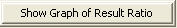
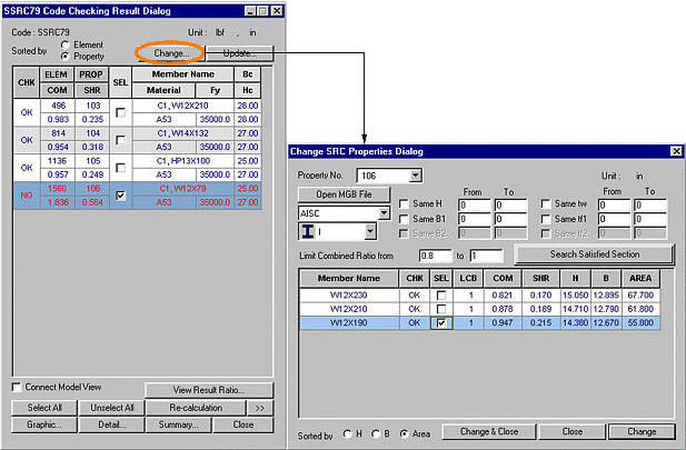
1. SSRC79
SSRC79 Code Checking Results dialog box
CHK: Status of strength verification results by members
= "OK": stress in the member is within the allowable stress range
= "OK*": stress in the member is within the allowable stress range but exceeds the allowable slenderness ratio
= "NG": stress in the member exceeds the allowable stress range
= "NG*": stress in the member exceeds the allowable stress range and slenderness ratio
ELEM: Element number
PROP: Section property number
COM: Maximum Combined Interaction Ratio
SHR: Stress ratio for the shear force (Member shear stress /Allowable shear stress)
SEL: Member selection for section changes, re-verification of members/sections and production of results
Type: Symbol for sectional shape
= RBO: Unfilled steel box section encased in a rectangular concrete section
= RBC: Concrete filled steel box section encased in a rectangular concrete section
= RPO: Unfilled steel pipe section encased in a rectangular concrete section
= RPC: Concrete filled steel pipe section encased in a rectangular concrete section
= CBO: Unfilled steel box section encased in a circular concrete section
= CBC: Concrete filled steel box section encased in a circular concrete section
= CPO: Unfilled steel pipe section encased in a circular concrete section
= CPC: Concrete filled steel pipe section encased in a circular concrete section
= EBC: Concrete filled steel box section (Concrete Filled Tubular section)
= EPC: Concrete filled steel circular section (Concrete Filled Tubular section)
= RIB: I-steel section encased in a rectangular concrete section
= CIB: I-steel section encased in a circular concrete section
Rebar: Standard rebar size and the number of main rebars entered by the user
Notation: n1 - n2 - #xx(Dxx).
(n1: number of main rebars, n2: number of rows of main rebars, #xx(Dxx): standard size for main rebars).
Member Name: Steel section name entered by the user or stored internally by the program
Material: Steel material name entered by the user or stored internally by the program
Fy: Yield strength of steel
f'c: Concrete design compressive strength
Fyr: Design yield strength for main rebars
Bc, Hc: Width, height (depth) of concrete section
LCB: Load combination yielding the maximum combined stress ratio
Len: Member length based on local node coordinates of the analysis model
Ly, Lz: Unbraced lengths for the member buckling about strong (y-Axis) and weak (z-Axis) axes respectively
Pa: Member axial force. (Pa > 0: tension, Pa < 0: compression)
My, Mz: Bending moments about the member's strong and weak axes respectively
Ky, Kz: Effective buckling length factors for the member buckling about the member's strong and weak axes respectively
Cmy, Cmz: Coefficients for moment magnification about the member's strong and weak axes respectively
fa: Compression (tension) stress in the member's axial direction
fby, fbz: Bending stresses due to moments about the member's strong and weak axes respectively
Fa: Allowable compression (tension) stress in the member's axial direction
FBy, FBz: Allowable bending stresses due to moments about the member's strong and weak axes respectively
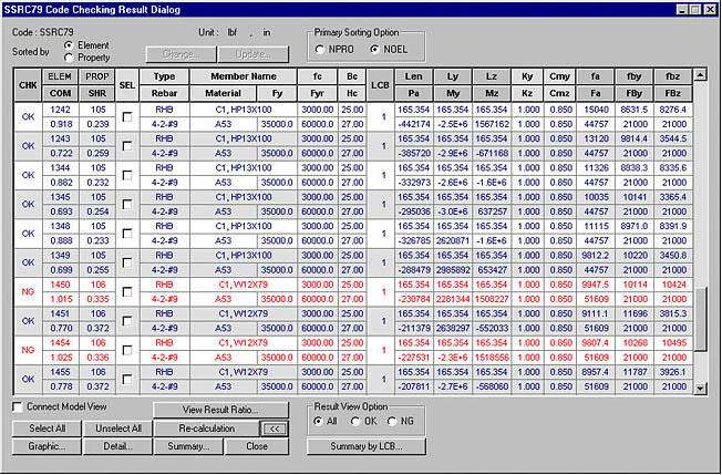
2. AIJ-SRC01 (available upon request)
AIJ-SRC01 Code Checking Result dialog box
Fy: Yield strength of steel
Fc: Concrete design compressive strength
mFy: Design yield strength of main rebars
rDy, rDz: Amplification factors applied to the bending moments about the strong and weak axes of the reinforced concrete column portion of a slender column.
sN: Allowable axial force of the structural steel portion
rN: Allowable axial force of the reinforced concrete portion
sMy, sMz: Allowable bending moments about the strong and weak axes of the structural steel portion
rMy, rMz: Allowable bending moments about the strong and weak axes of the reinforced concrete portion
Refer to SSRC79 for other contents.
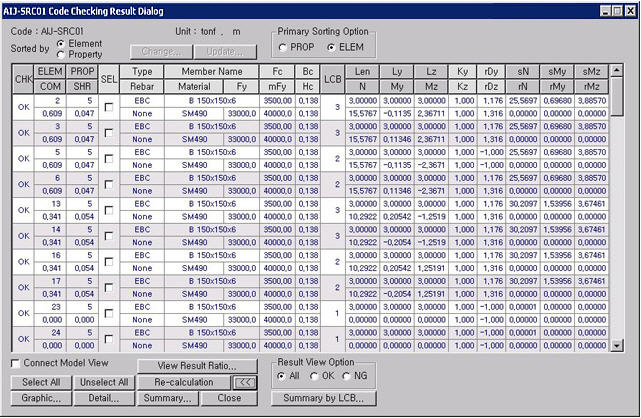
3. AIK-SRC2K (available upon request)
AIK-SRC2K Code Checking Result dialog box
Identical to SSRC79
Display the strength verification results for the maximum combined stress ratios by Elements or by Properties. "Sorted by Property" displays the strength verification results of the element producing the maximum combined stress ratio among all the members attributed to the section property.
Once Property is selected, SEL controls all the elements attributed to the same section properties.
Re-verify the strengths of the selected members. When the strength re-verification is executed from the results displayed by section properties all the elements attributed to the same sections are included.
Note
"Sorted by Property" produces the results of the maximum combined stress ratios representing all the members of same properties.
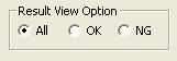
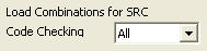
= All: Produce all the strength-verified results in the Checking Results dialog box
= OK: From the strength-verified results, display only the results that have met the design requirements (OK) in the Checking Results dialog box
= NG: From the strength-verified results, display only the results that have not satisfied the design requirements (NG) in the Checking Results dialog box
Section Change
Provide sections satisfying the conditions for the selected elements. If reinforcing steel is used in the concrete section (RBO, RBC, RPO, RPC, CBO, CBC, CPO, CPC, RIB or CIB), list only the sections that do not interfere with the concrete sections and rebars. The spacing for structural steel and rebars are provided in Modify SRC Section Data.
Member Name: Section names
CHK: Status of strength verification results
= "OK": stress in the section is within the allowable stress range
= "NG": the stress in the section exceeds the allowable stress range
SEL: Select the sections to be changed
LCB: Load combination yielding the maximum combined stress ratio
COM: Maximum Combined Interaction Ratio
SHR: Stress ratio for the shear force (Member shear stress /Allowable shear stress)
H: Height (depth) of steel section
B: Width of steel section
Area: Cross sectional area of steel section
(MGB files containing section data created by the user can be used. Only DB/User Section is included for the construction of DB)
Select the shape of the steel section to be changed (select among RBO, RBC, RPO, RPC, CBO, CBC, CPO, CPC, RIB & CIB)
I - RIB, CIB
B(Open) - RBO, CBO
B(Closed) - RBC, CBC
B(Filled) - EBC
P(Open) - RPO, CPO
P(Closed) - RPC, CPC
P(Filled) - EPC
Note that the concrete section remains unchanged when Open and Closed sections are selected, whereas the concrete section is automatically changed when a Filled section is selected.
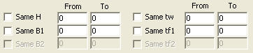
Select the range of sectional dimensions to be changed Fill in the Checkbox if the desired section dimensions are required to coincide with the current section dimensions in use. Enter dimensions in the present unit system in the From and To fields to assign the ranges.
Enter dimensions only in the From fields when the new section is to retain given dimensions.
Perform strength verification for the SRC sections. The steel sections must satisfy the constraints.
After strength verification for the selected sections is carried out, save the changed results in the SRC strength verification file (.GD4) then close the dialog box.
After strength verification for the selected sections is carried out, save the changed results in the SRC strength verification file (.GD4).
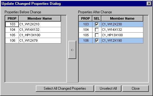
Update Changed Sections
Properties Before Change presents the sectional properties used in the initial analysis.
Properties After Change presents the changed sectional properties after completing the final strength verification.
If Update is executed, the analysis and strength verification results are deleted. The updated model needs to be reanalyzed to re-verify the strengths.
In order to reanalyze the updated model
and re-verify the strengths, click
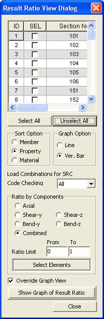
Plot strength verification results in graphs
Plot the strength verification results in graphs by materials, sections or members. (Plot strength verification results in graphs)
Option to produce the graph in a new View. (If checked, the graph is produced in the existing view)
Produce the ratio graph of strength verification results for members satisfying the conditions for selection
| ||
|
|
 : Display the applicable
code for strength verification.
: Display the applicable
code for strength verification.
 : Display the unit system
selected by the user.
: Display the unit system
selected by the user. : Select all members
 : Cancel the selection
of all members
: Cancel the selection
of all members
 : Check in the option
to select and highlight the selected members in Model View.
: Check in the option
to select and highlight the selected members in Model View. : Display detail strength
verification results
: Display detail strength
verification results : Display simplified
strength verification results
: Display simplified
strength verification results : Produce the strength
verification results in summary calculations for the selected members.
: Produce the strength
verification results in summary calculations for the selected members.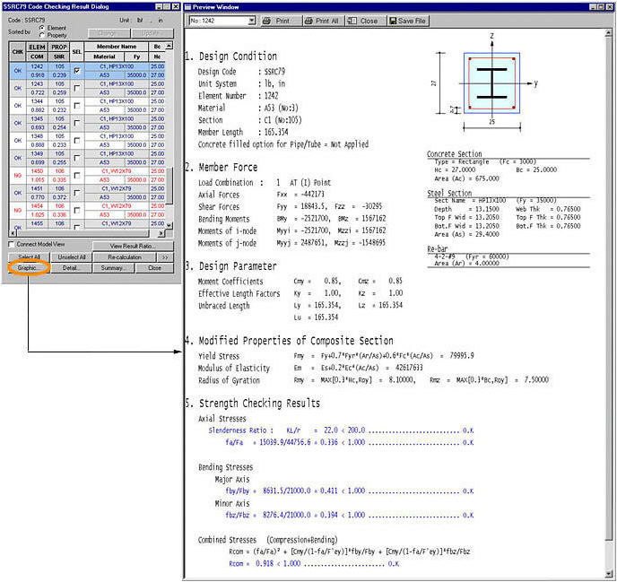
 : Produce the strength
verification results in detail calculations for the selected members.
: Produce the strength
verification results in detail calculations for the selected members.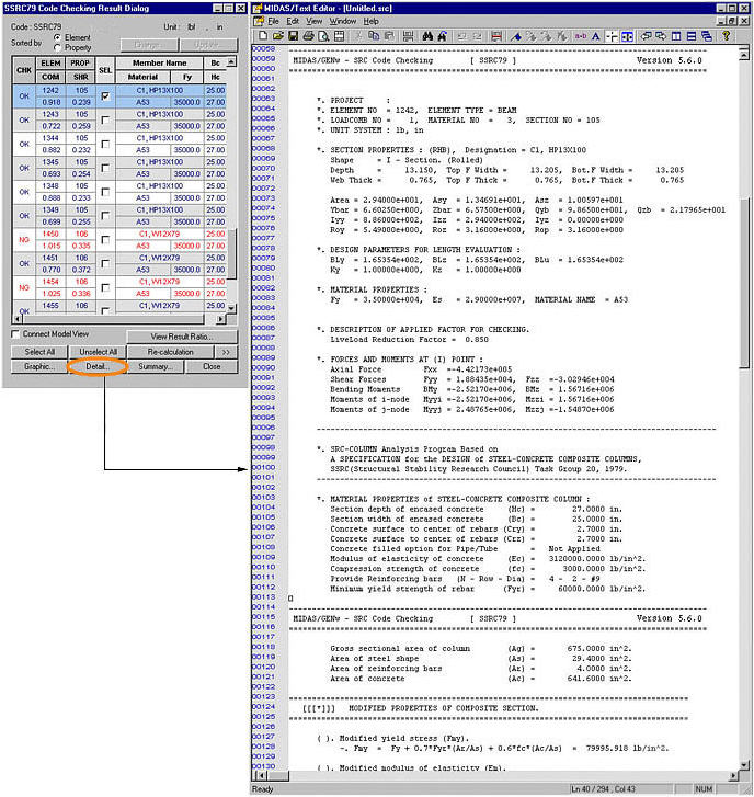
 : Produce the summary
list of strength verification results for the selected members.
: Produce the summary
list of strength verification results for the selected members.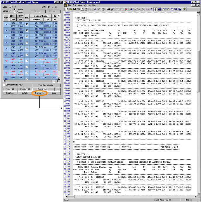
 : Produce the strength
verification results of all the selected members based on the steel design
load combinations
: Produce the strength
verification results of all the selected members based on the steel design
load combinations : Close the dialog box
 : Select the property
number to be changed
: Select the property
number to be changed : Open an MGB file to
be used for the section DB
: Open an MGB file to
be used for the section DB : Select the DB for
which sections are to be changed
: Select the DB for
which sections are to be changed
 :
: : Select the combined
stress ratio range within which the sections are to be changed.
: Select the combined
stress ratio range within which the sections are to be changed.
 : Select an option for sorting
the sections' strength verification results.
: Select an option for sorting
the sections' strength verification results.
 : Update the modeling
properties with the changed sections after completing strength verification.
: Update the modeling
properties with the changed sections after completing strength verification.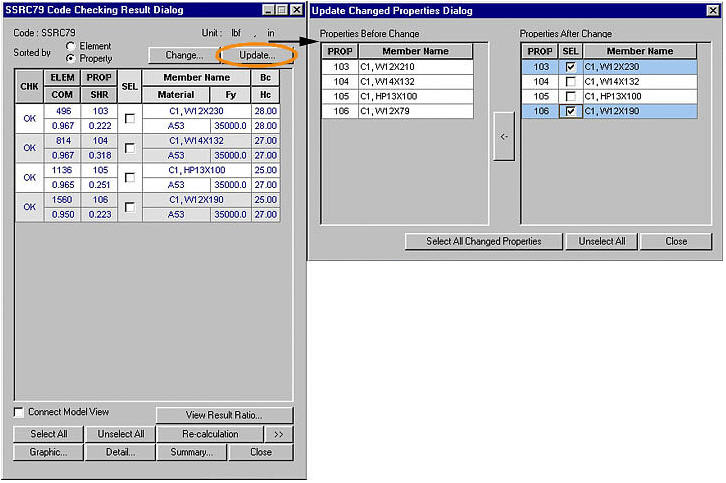
 : Auto-select only the
changed properties.
: Auto-select only the
changed properties. : Update the modeling
properties with the selected sections.
: Update the modeling
properties with the selected sections. then click
  .
.
 : Cancel all the selection

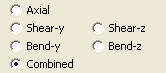 : Select a ratio component
for output
: Select a ratio component
for output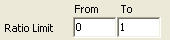 : Select a ratio range
for output
: Select a ratio range
for output : Select members satisfying
Sorting Option, Load Combinations, Ratio component and Ratio Limit in
Model View.
: Select members satisfying
Sorting Option, Load Combinations, Ratio component and Ratio Limit in
Model View.