Ductile Design
| ||||||||||||||||||||||||||||||
|
| ||||||||||||||||||||||||||||||
|
| ||||||||||||||||||||||||||||||
|
Considering the flexural capacity of reinforced concrete beam and column, automatically design beam and column members.
The process of automatic design is outlined as below.
Step 1: Apply “Special Provisions for Seismic Design” for the design of beam members
Step 2: Calculate design member forces of column members (Calculate end moments that result in hinges at beam ends)
Step 3: Using the member forces and axial forces calculated from Step 2, perform automatic design for column members
Note
1. Applied design codes: ACI318-89/95/99/02, TWN-USD92, KCI-USD99, KCI-USD03 2. When “Special Provisions for Seismic Design” is applied | ||||||||||||||||||||||||||||||
|
| ||||||||||||||||||||||||||||||
|
| ||||||||||||||||||||||||||||||
|
| ||||||||||||||||||||||||||||||
|
From the Main Menu select Design > RC Strong Column-Weak Beam > Ductile Design. | ||||||||||||||||||||||||||||||
|
| ||||||||||||||||||||||||||||||
|
| ||||||||||||||||||||||||||||||
|
The details of each item for Strong Column Design and Weak Beam Design are identical to those for general beam/column design.
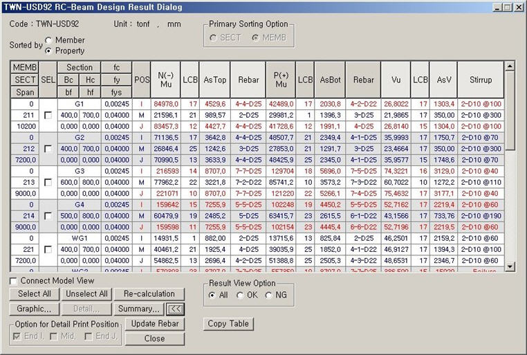
TWN-USD92 Weak Beam Design Result dialog box
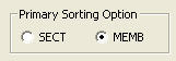
MEMB: Member number
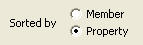
SECT: Section property number
Span: Length of beam member
SEL: Select members for redesign and production of results
Note
Section: Section Name
Bc, Hc: Width, height (depth) of beam member
bf, hf: Width, thickness of the flange of T-shape section
fck: Design compressive strength of concrete
fy: Design yield strength of main rebars
fys: Design yield strength of shear rebars
POS: Automatic design positions (I, M, J)
The design results for M reflect the automatic design for the maximum negative and positive moments and shear forces at 1/4, 1/2 & 3/4 points.
CHK:
Status of automatic design results (Results are produced in the
= "OK": Automatic design results satisfy the design strength for the factored negative moment, positive moment and shear force
= "N**": Automatic design results do not satisfy the design strength for the factored negative moment
= "*P*": Automatic design results do not satisfy the design strength for the factored positive moment
= "**V": Automatic design results do not satisfy the design strength for the factored shear force
= "NP*": Automatic design results do not satisfy the design strength for the factored negative and positive moments
= "*PV": Automatic design results do not satisfy the design strength for the factored positive moment and shear force
= "N*V": Automatic design results do not satisfy the design strength for the factored negative moment and shear force
= "NPV": Automatic design results do not satisfy the design strength for the factored negative moment, positive moment and shear force
N(-)Mu, LCB: Maximum factored negative moment occurring in the relevant member or section and the corresponding load combination
AsTop: The area of required to rebars calculated by the program. The larger of the calculated rebar area and the minimum rebar quantity specified in the codes is presented.
Rebar(AsTop): The required number of rebars using the standard sizes specified by the user is presented.
When the reinforcing placement requires more than 2 layers, place the rebars up to the second layer.
= for 1 rebar-layer ("xx-Dyy")
xx is the number of top rebars and yy is the standard rebar size designation
= for 2 rebar-layers ("xx-yy-Dzz")
xx is the number of upper layer top rebars, yy is the number of lower layer top rebars and zz is the standard rebar size designation
P(+)Mu, LCB: Maximum factored positive moment occurring in the relevant member or section and the corresponding load combination
AsBot: The area of required bottom rebars calculated by the program. The larger of the calculated rebar area and the minimum rebar quantity specified in the codes is presented.
Rebar(AsBot): The required number of rebars using the standard sizes specified by the user is presented.
When the reinforcing placement requires more than 2 layers, place the rebars up to the second layer.
= for 1 rebar-layer ("xx-Dyy")
xx is the number of bottom rebars and yy is the standard rebar size designation.
= for 2 rebar-layers ("xx-yy-Dzz")
xx is the number of lower layer bottom rebars, yy is the number of upper layer bottom rebars and zz is the standard rebar size designation.
Vu, LCB: Maximum factored shear force occurring in the relevant member or section and the corresponding load combination
AsV: Reinforcing steel section area required for the shear force calculated by the program. The larger of the calculated rebar area and the minimum rebar quantity specified in the codes is presented.
Note
Stirrup: The required rebar spacing based on AsV using the standard sizes for sub-rebars entered by the user
The following are displayed for Stirrup based on the automatic design results:
= "xx-Dyy@zzz"
xx is the number of stirrups, yy is the standard rebar size designation and zzz is the rebar spacing (unit: mm).
= "Failure": When the design shear strength Vs does not satisfy the Clause 7.3.3.(8) in TWN-USD92 (When an increase in section is required)
TWN-USD92 Strong Column Design Result dialog box
MEMB: Member number
SECT: Section property number
SEL: Select members for redesign and production of results
Note
Section: Section Name
Bc, Hc: Width, height (depth) of column section
Height: Height of column member
fck: Design compressive strength of concrete
fy: Design yield strength of main rebars
fys: Design yield strength of shear rebars
CHK:
Status of automatic design results (Results are produced in the
= "OK": Automatic design results satisfy the design strength for the factored axial force, moment and shear force
= "P**": Automatic design results do not satisfy the design strength for the factored axial force
= "*M*": Automatic design results do not satisfy the design strength for the factored moment
= "**V": Automatic design results do not satisfy the design strength for the factored shear force
= "PM*": Automatic design results do not satisfy the design strength for the factored axial force and moment
= "*MV": Automatic design results do not satisfy the design strength for the factored moment and shear force
= "P*V": Automatic design results do not satisfy the design strength for the factored axial force and shear force
= "PMV": Automatic design results do not satisfy the design strength for the factored axial force, moment and shear force
LCB: Load combination yielding the maximum factored load ratio determined from the P-M diagram. The program examines all the load combinations and sectional locations of the relevant member or section property to find the maximum ratio.
Pu: Factored compression (tension) force acting on the column member under the load combination displayed in LCB
= Pu > 0: Compressive axial force acting in the member's axial direction
= Pu < 0: Tensile axial force acting in the member's axial direction
Rat-P:
Ratio of the factored axial force ( design strength is unsatisfactory even if the rebar quantity is increased to the maximum rabar ratio or the minimum rebar spacing for the relevant column section.
Mc: Factored bending moment in the column member under the load combination displayed in LCB. The value is calculated as follows:
Rat-M:
Ratio of the factored bending moment (
Ast: The quantity of main rebars auto-calculated by the program. This is larger than the minimum rebars specified by the codes.
V-Rebar: Optimum rebar size and the number of rebars, which satisfy the design conditions (minimum rebar spacing, minimum/maximum reinforcing steel ratios).
"n1 - n2 - Dxx(#xx)"
n1: number of main rebars, n2: number of rows of main rebars, Dxx: designated standard size of main rebars
Vu: Maximum factored shear force of the relevant member or section (The load combination number that results in the maximum factored shear force is displayed in the summary and detail calculations.)
Rat-V:
Ratio of the factored shear force (
As-H: Reinforcing steel section area required for the shear force calculated by the program, with the lower bound being the minimum rebar quantity specified in the codes.
Note
H-Rebar: Shear rebar placement spacing expressed in terms of As-H using the sub-rebar standard sizes entered by the user.
The following are displayed for H-Rebar based on the automatic design results:
"Dxx @yyy": xx is the designated standard rebar size, yyy is the rebar spacing (unit: mm).
"Failure": When the design shear strength Vs does not satisfy the Clause 7.3.3(8) in TWN-USD92 (When an increase in section is required)
| ||||||||||||||||||||||||||||||
|
|
 Weak
Beam Design Results
Weak
Beam Design Results state for convenience)
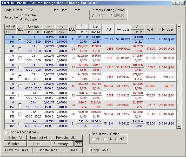
 ) to the design axial
strength (
) to the design axial
strength (  ). The ratio larger than 1.0 signifies that the
 ) to the design bending
moment strength (
) to the design bending
moment strength (  ). The ratio larger than 1.0 signifies
that the design strength is unsatisfactory even if the rebar quantity
is increased to the maximum rebar ratio or the minimum rebar spacing for
the relevant column section.
). The ratio larger than 1.0 signifies
that the design strength is unsatisfactory even if the rebar quantity
is increased to the maximum rebar ratio or the minimum rebar spacing for
the relevant column section. )
to the design shear strength (
)
to the design shear strength (  )
)