Section Optimization of structural steel and steel-concrete composite
sections is carried out through iterative analysis based on the user defined
displacement limit, analysis results and the results of design check.
In the case of steel-concrete composite sections, the concrete section
sizes and structural steel section sizes are changed in the process of
optimization, and the section shape and the amount of reinforcing steel
cannot be changed.
From the Main
Menu select Design
> Displacement
Optimal Design.
For optimization design per lateral design
control, enter the lateral displacement limit and the condition of design
limit.
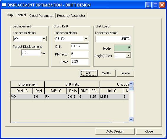
Displacement
Optimization-Disp. Control dialog box
Disp. Control
Displacement
Enter the displacement control information
related to wind loads.
Load Case
Name: Wind load case for which lateral displacement will be controlled
Target
Displacement: Maximum permitted displacement
Story Drift
Enter the inter-story drift control information
related to seismic loads.
Load Case
Name: Seismic load case for which inter-story drift will be controlled
Drift Ratio:
Ratio of allowable inter-story drift to story height
RMFactor:
Response Modification Factor
Scale:
Scale-up Factor representing the ratio of static seismic base shear to
that of response spectrum analysis
Unit Load
Load Case
Name: Static load case name for a unit load
Node:
Node number at which a unit load is acting
Angle (CCW):
Direction of the unit load
: Add the lateral displacement/drift
control data entered or add a unit load.
: Update lateral displacement/drift
control data or a unit load, which have been previously defined
: Delete the selected lateral
displacement/drift control data or a unit load.
Select the members (Steel Column, SRC Column,
Beam & Brace) for which optimum design will be performed.
Sect. DB
Select the database for the members. The
program provides the database for , , , , , , , , , , . uses welded built-up sections whose member dimensions are
defined by D1-D6 and the thickness data are defined in.
If is selected, welded member sections defined in will be used.
Max (H-B)
Enter the difference between the larger and
smaller side dimensions.
Note
A square section will have a ??value for Max (H-B).
H
Height (depth) of a section
Min:
Minimum dimension to be applied to optimal design
Max:
Maximum dimension to be applied to optimal design
Inc:
Dimensional increment between the minimum and maximum dimensions
B
Breadth (width) of a section
Min:
Minimum dimension to be applied to optimal design
Max:
Maximum dimension to be applied to optimal design
Inc:
Dimensional increment between the minimum and maximum dimensions
Width-Thk. Ratio
Limit for width to thickness ratio
Auto:
Auto-set to the maximum width to thickness ratio specified by the design
standard
User:
Maximum width to thickness ratio defined by User
No Limit:
No limit for maximum width to thickness ratio imposed
Flange
Width to thickness ratio for Flange
Out:
One end free and one end supported
In:
Both ends supported
Web
Width to thickness ratio for Web
Out:
One end free and one end supported
In:
Both ends supported
Allowable
Ratio
Allowable stress and strength ratio, which
will become bases for optimal design
Column Section
Limiting condition for optimal design of
columns
Default:
Use optimally designed column sizes.
Uni-Sect:
Use a uniform section for each story.
Optimum:
Use optimally designed column sizes such that lower column section dimensions
are larger than those for upper columns.
Parameter of Built Up
Section
Built-Up
Joint
Limitation for column sizes as to whether
the outer or inner dimensions of columns (above and below) should be maintained
(flushed)
External:
Outside flushed
Internal:
Inside flushed
Plate Thickness
Enter the thicknesses of flanges and webs
to be used in optimal design.
Click to prompt the Plate Thickness
Data entry dialog box.
Plate
Thickness Data dialog box
Thickness
List: Thickness database
Selected
List: Thicknesses selected from the database
: Select specific thicknesses
in Thickness List and update Selected List.
: Select all the thicknesses
in Thickness List and update Selected List.
: Delete all the selected
thicknesses in Selected List.
: Delete the selected thicknesses
in Selected List.
User Input:
Thickness is directly entered by User.
: The user defined thickness
is added to the Selected List.
Chk. Dgn.
: Select
the sections for which optimum design will be performed
ID
: Section
number
Origin
Section :
Display the dimension of the members entered by the user. This part cannot
be modified
Section
Name
Type :
Section type
Size :
Section size
Shape : Section shape
Para. :
Select the design control limits to be applied to optimal design
G :
Design control limit for every member type
P :
Design control limit for every section type
Sect. DB
Select the database for the members. The
program provides the database for 15 different types including AISC, BS,
KS, etc.
Built-up sections are based on member dimensions
(H & B) and the thickness data are defined in Plate Thk. If User is
selected,
welded member sections defined by user in
Use User Defined Section will be used.
Max (H-B)
Enter the difference between the larger and
smaller side dimensions.
Note
A square section will have a ??value for Max (H-B).
H
Height (depth) of a section
Min:
Minimum dimension to be applied to optimal design
Max:
Maximum dimension to be applied to optimal design
Inc:
Dimensional increment between the minimum and maximum dimensions
B
Breadth (width) of a section
Min:
Minimum dimension to be applied to optimal design
Max:
Maximum dimension to be applied to optimal design
Inc:
Dimensional increment between the minimum and maximum dimensions
Width-Thickness
Ratio
Limit for width to thickness ratio
Method
Auto:
Auto-set to the maximum width to thickness ratio specified by the design
standard
User:
Maximum width to thickness ratio defined by User
No Limit:
No limit for maximum width to thickness ratio imposed
F.Out:
Width to thickness ratio for one end free and one end supported Flange
F.In:
Both ends supported width to thickness ratio for Flange
W.Out:
One end free and one end supported width to thickness ratio for Web
W.In:
Both ends supported width to thickness ratio for Web
Allow
Allowable stress and strength ratio, which
will become bases for optimal design
Uniform Sect.
Limiting condition for optimal design of
columns
Default:
Use optimally designed column sizes.
Uni-Sect:
Use a uniform section for each story.
Optimum:
Use optimally designed column sizes such that lower column section dimensions
are larger than those for upper
columns.
Built-Up
Joint
Limitation for column sizes as to whether
the outer or inner dimensions of columns (above and below) should be maintained
(flushed)
External:
Outside flushed
Internal:
Inside flushed
Plate Thickness
Enter the thicknesses of flanges and webs
to be used in optimal design.
Click to prompt the Plate Thickness
Data entry dialog box.
: Select all sections for
which optimal design will be performed
: Cancel the selection of
all sections.
: Change the design control
limit of the selected section.
: Perform optional design.
Dsiplacement Optimal Design Results
Function
Display the output for optimization design
per lateral displacement control, sort the optimal design results in various
forms, and reflect the change of sections in the model.
Sect. ID
: Section number
Sect. Name
: Section name
Memb. Type
: Member type
Origin Sect.
: Member section defined by the user
Proposal
Sect. Member section designed optimally
CHK
: Display the status of strength verification results
COM
: Combined stress ratio(Combined strength ratio) due to the strength verification
results
LCB
: Maximum combined stress ratio
Weight
: Structure(1) and the total weight of the structure after optimal design
Steel
: Total weight of steel
RC
: Total weight of concrete
Max. Displacement
: Maximum displacement for every load case
Max. Story
Drift Ratio : Maximum story drift for every load case and the location
Output Data
: Produce the results in
a graphic format
: Produce the results in
a text format
: Display the results in various
forms of charts. The types of output charts are as follows
Tread of
Total Displ. Change : Variation graph of maximum displacement of
each optimization step.
Displ.
Participation Factor per Weight : Variation graph of displacement
participation factor per unit weight for each member
section at each optimization step
Displ.
Participation Fator : Variation graph of displacement participation
factor for each member section at each optimization
step
Design
Ratio and Steel Weight : Variation graph of combined stress ratio(Combined
srength ratio) and variation graph of
steel weight for each member section before
and after optimal design.
: Incorporate the sections designed optimally into the original
model
 Disp. Control
 : Add the lateral displacement/drift
control data entered or add a unit load.
: Add the lateral displacement/drift
control data entered or add a unit load. : Update lateral displacement/drift
control data or a unit load, which have been previously defined
: Update lateral displacement/drift
control data or a unit load, which have been previously defined : Delete the selected lateral
displacement/drift control data or a unit load.
: Delete the selected lateral
displacement/drift control data or a unit load.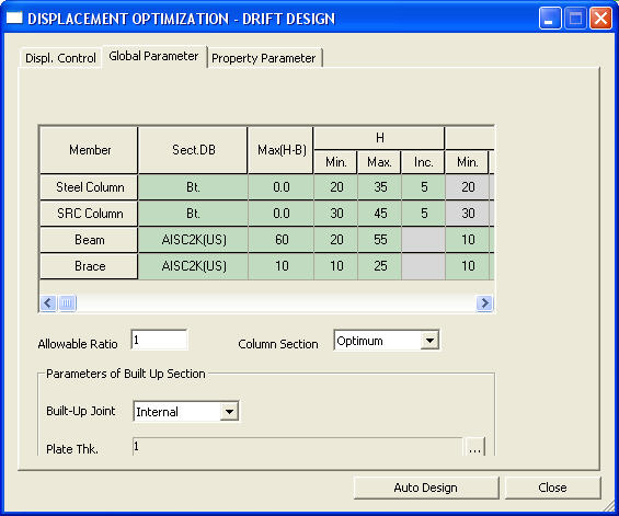
 ,
,  ,
,  ,
,  ,
,  ,
,  ,
,  ,
,  ,
,  ,
,  ,
,  .
.  .
If
.
If  will be used.
 to prompt the Plate Thickness
Data entry dialog box.
to prompt the Plate Thickness
Data entry dialog box.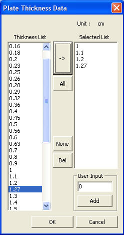
 : Select specific thicknesses
in Thickness List and update Selected List.
: Select specific thicknesses
in Thickness List and update Selected List. : Select all the thicknesses
in Thickness List and update Selected List.
: Select all the thicknesses
in Thickness List and update Selected List. : Delete all the selected
thicknesses in Selected List.
: Delete all the selected
thicknesses in Selected List. : Delete the selected thicknesses
in Selected List.
: Delete the selected thicknesses
in Selected List.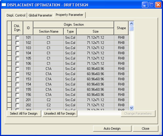
 : Select all sections for
which optimal design will be performed
: Select all sections for
which optimal design will be performed : Cancel the selection of
all sections.
: Cancel the selection of
all sections. : Change the design control
limit of the selected section.
: Change the design control
limit of the selected section. : Perform optional design.
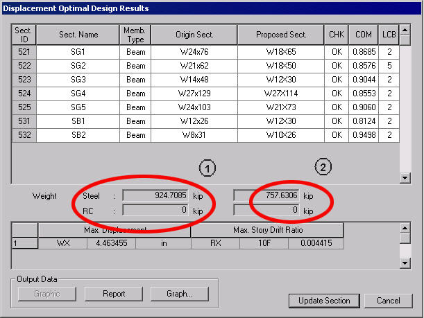
 : Produce the results in
a graphic format
: Produce the results in
a graphic format : Produce the results in
a text format
: Produce the results in
a text format : Incorporate the sections designed optimally into the original
model
: Incorporate the sections designed optimally into the original
model