1. The
service load combinations for footing design must be defined prior to
undertaking footing design. Use Results > Combinations
to define the load combinations. Select the service and factored loads
in .
2. The
data entries are deleted when the program is terminated. The contents
of the display window for calculation results cannot be saved.
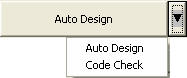
3. The
footing design can be operated in two modes: Auto
Design and Code Check.
Use to the right to convert from one mode to the other.
Note
The reinforcing cover thickness (dc) of the footing does not change due
to a mode conversion.
4. The
column size is set to the largest member size among all the members connected
to the support node. For a circular section, the diameter is used for
the column dimension. For other cross-sectional shapes, outer dimensions
are used as rectangular shapes.
When the sectional dimensions of columns must be changed due to pedestals
or base plates, use .
Can be accessed only in the Post-processing Mode.
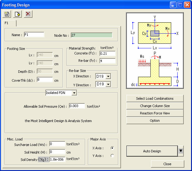
From the Main
Menu select Design > Footing Design.
Footing Design dialog box
Multi-Footing Design Function
Generate multiple footing groups.
: Reset the Footing Design dialog box to the original state.
: Add a footing group for multi-footing design.
: Delete the current footing group.
Name
Enter the name of the footing to be designed.
The name appears as the title of the output.
Node No
Enter the node numbers where the footings
are located.
Click the node number field and pick the
relevant nodes in the working window.
The node numbers can also be directly entered
in the node number field.
Footing Size
Enter the footing data.
Lx
: Footing dimension in X-axis
Ly
: Footing dimension in Y-axis
The footing sizes are automatically calculated
in the "Auto Design"
mode of spread footings.
The pile cap sizes are automatically calculated
based on the spacing between the piles and the edge distance. The user
can not define the pile cap sizes.
Depth (D):
Thickness of footing
Auto-calculated in "Auto
Design" mode.
Cover Thk
(dc): Concrete cover to the center of main rebars
Material Strength
The user may directly enter the values if
not preassigned.
Concrete
(f'c): Compression strength of concrete
Re-bar (fy):
Yield strength of rebars
Re-bar Size
Enter the standard rebar sizes to be used.
Only the designated sizes can be used. The rebars are designed using 3different
sizes equal to and larger than the size specified.
X Direction:
Standard rebar size in the X-direction
Y Direction:
Standard rebar size in the Y-direction
Isolate FDN / Pile FDN
Convert the foundation type mode (Spread
footing & Pile Cap).
Misc. Load
Specify additional loads to be considered
in the design. The nodal reactions from the analysis results are automatically
reflected.
Surcharge
Load (Ws): Load per unit area on the surface
Soil Height
(H): Height from the top of footing to the ground level
Soil Density
(γq): Soil density
Major Axis
Select the direction of the major axis. The
major axis is used to determine the effective depths of footing and layout
the piles.
X Axis:
Set X-axis as the major axis
Y Axis:
Set Y-axis as the major axis
Select the service and factored load combinations for footing design.
Change the column (pedestal) sizes to be used in design.
Display the nodal reactions.
Change all types of parameters related to design.
The program automatically searches for an adequate footing size and the
number of piles. It looks for satisfactory dimensions by checking all
the entered nodes and load combinations. The results are produced only
for the node subjected to the most severe load combination. When the node
numbers determining the footing size (Lx, Ly) and the thickness (depth)
of the footing are different, the calculation results are produced for
the node that governs the footing size.
The arrow button to the right selects either Auto
Design or Code Check.
Calculations are based on the entered data, governed by the worst load
combination for footing design.
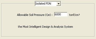
Isolate FDN
Function
Enter the required data for the design of
spread footings.
Entry
Isolate
FDN dialog box
Allowable
Soil Pressure (Qe)
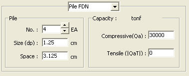
Pile FDN
Function
Enter the required data for the design of
pile caps.
Entry
Pile
FDN dialog box
Pile
No.:
Number of piles (maximum 24 piles).
Not required in "Auto
Design" mode.
Size (dp):
Diameter of a pile.
Space:
Pile spacing (larger than 2.5 X dp).
Note
Appropriate pile placement is carried out by the program reflecting the
major axis and using the built-in database. The positions of piles can
not be changed separately.
Capacity
Compressive
(Qa): Allowable compression capacity of a pile.
Tensile
(|QaT|): Allowable tension capacity of a pile. Enter "0"
when the piles cannot resist tension.
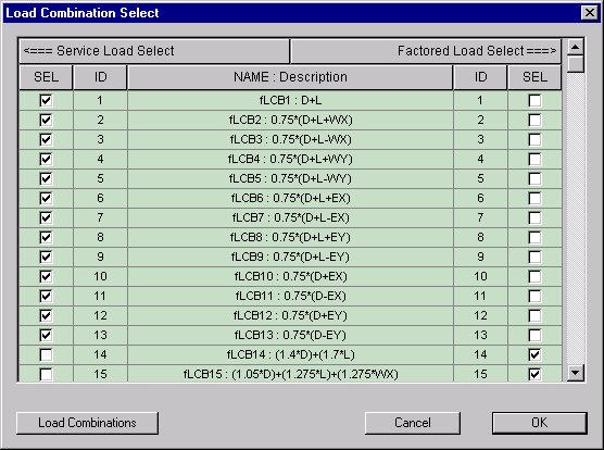
Load Combination Select
Function
Select the service and factored load combinations
for design.
Load combinations must be defined prior
to designing foundation.
Entry
Load
Combination Select Table dialog box
Service
Load Select
Select the load combinations in service loads in 'SEL" to the left.
Factored
Load Select
Select the load combinations in factored loads in 'SEL" to the right.
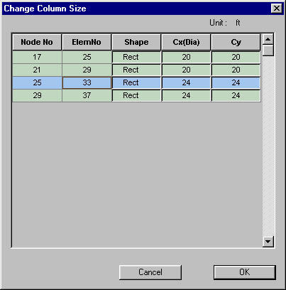
Change Column Size
Function
Change the sizes and shapes of the columns
or pedestals.
Entry
Change
Column Size Table dialog box
Shape
Enter the shapes of columns or pedestals. Select for rectangular
and for circular shapes.
Cx (Dia)
Rectangular column dimension in the X-direction or the diameter of a circular
column.
Cy
Rectangular column dimension in the Y-direction.
Reaction Force View
Function
Show the reaction forces.
Live load reduction factor is set to 1.0,
if a value is not entered previously by the user. The displayed reaction
values reflect the Live Load Reduction Factor.
Entry
Reaction
Force View Table dialog box
Node ID
Select the node number of interest. Only the numbers entered in the Node
ID field of the Foundation Design window can be selected.
When "Applied Forces and Moments" is set to "Axial Forces
Only" in the Option dialog box, Mx and My are set to '0' irrespective
of the true values of the reactions.
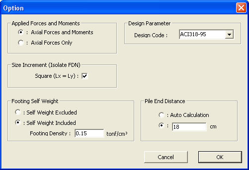
Option
Function
Change all types of parameters related to
design.
Entry
Option
dialog box
Applied Forces and Moments
Axial Forces
and Moments
Design footings using axial forces and moments applied to the nodes.
Axial Forces
Only
Design footings using only the axial forces applied to the nodes. If selected,
the moment is set to '0' irrespective of the true values of the reactions.
Size Increment (Isolate
FDN)
Square
(Lx=Ly): If selected in Auto-Design for spread footings, the transversal
and longitudinal lengths of the footings are increased by the specified
increment to design square footings.
If not selected, the dimensions of the footings
are increased to appropriate ratios reflecting the applied moments and
soil reactions. The ratios of the two sides do not exceed 2.
Design Parameter
Design Code
Enter one of the following design codes:
ACI318-02:
American Concrete Institute
ACI318-95:
American Concrete Institute
BS8110-97:
British Standard
KCI-USD99:
Korean Concrete Institute
KCI-USD99(Build.):
Korean Concrete Institute
KBC-USD05:
Korean Building Code
KBC-USD05
(Build.): Korean Building Code
Strength
Reduction Factors
Enter strength reduction factors.
For Flexure
(b): Strength reduction factor for bending moment
For Shear
(v): Strength reduction factor for shear force
Footing Self Weight
Self Weight
Excluded
Design footings using only the reactions excluding the self-weights.
Self Weight
Included
Design forces include the self-weights in addition to the reactions.
Footing
Density
Enter the footing density.
Pile End Distance
Auto Calculation
Auto-calculate the end distance of piles. The end distance is calculated
as 1.25 X pile diameter.
Or, the
user may directly enter the pile end distance.
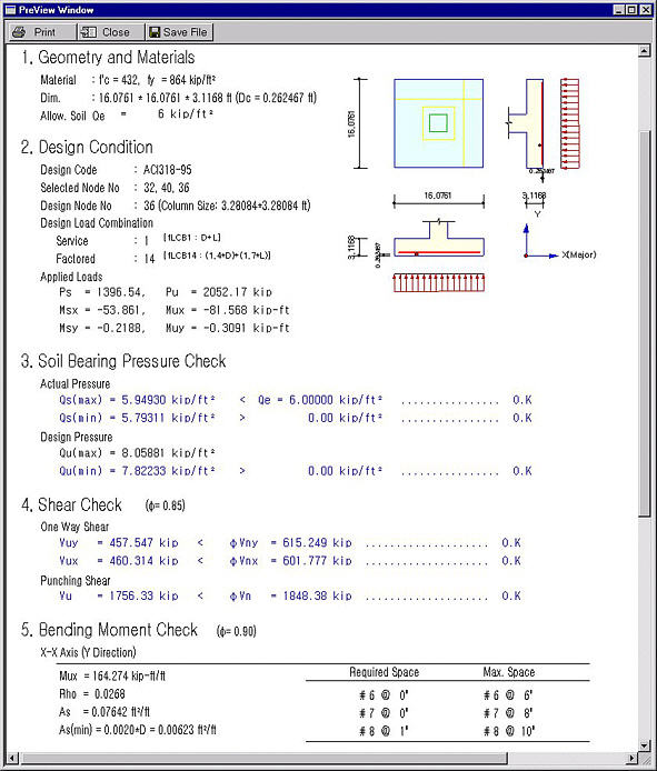
Produce Calculation Results
Calculation
Results Preview window
1. Geometry and Materials
Display the size, strength, etc.
2. Design Condition
Design
Code: Applied design code
Selected
Node No: Node numbers entered by the user
Design
Node No: Design node number with the most severe design condition.
Design Load Combination
Service:
The most severe load combination in service loads.
Factored:
The most severe load combination in factored loads.
Applied
Loads : Applied design loads.
Ps, Msx,
Msy : Combined service loads.
Pu, Mux,
Muy : Combined factored loads.
3. Soil Bearing Pressure
Check (Spread footing)
Actual
Pressure
Calculated reactions in service loads (for allowable soil pressure checking)
Soil pressure is calculated based on the sum of the footing self-weight,
the earth load above the footing and the surcharge (if entered by the
user).
Design
Pressure: Calculated reactions in factored loads (for footing design)
The reactions for concrete design do not
consider the self-weight, earth load and the surcharge.
4. Pile Bearing Capacity
Check (Pile Cap)
Display the calculated pile reactions.
5. Shear Check
One Way
Shear
Display the results of checking one-way shear strength.
If the shear failure line crosses the pile heads in pile cap footings,
the tributary cross-section areas are calculated and reflected in the
calculation of shear force.
Punching
Shear
Display the results of checking two-way shear strength.
The effective depth used to calculate the shear strength is determined
by subtracting [cover thickness entered by the user + diameter of the
main rebars] from the footing depth.
Vup and Vnp are based on the maximum pile reaction. The critical
punching shear failure plane is located d/2 away from the pile face.
6. Bending Moment Check
Display the quantity and spacing of rebars
for the applied bending moments.
Effective depth (d) for major axis : Footing
depth (D) - Cover Thk.(dc)
Effective depth (d) for minor axis : Footing
depth (D) - [cover thickness (dc) + main rebar diameter]
The minimum rebars are calculated using the
minimum temperature rebars. The maximum rebars are not calculated.
X-X Axis
(Y Direction)
Calculation results due to moment about X-axis (for reinforcement in the
Y-direction).
Y-Y Axis
(X Direction)
Calculation results due to moment about Y-axis (for reinforcement in the
X-direction).
Required
Space
The spacing of rebars calculated.
Max. Space
Maximum rebar spacing based on code requirements.
 .
. to the right to convert from one mode to the other.
 .
.
 Multi-Footing Design Function
 : Reset the Footing Design dialog box to the original state.
 : Add a footing group for multi-footing design.
 : Delete the current footing group.
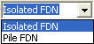


 for rectangular
and
for rectangular
and  for circular shapes.
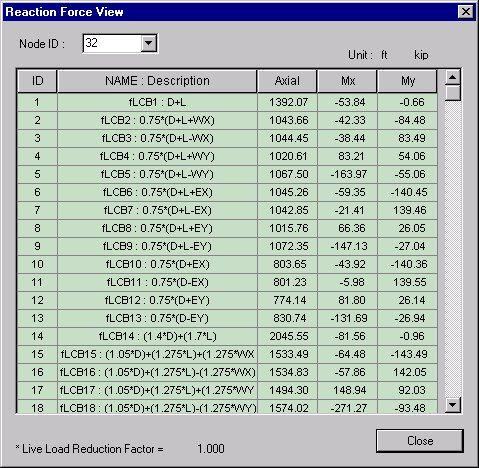
 b)
b)