Steel Code CheckAISC-LRFD2K, AISC-LRFD93, AISC-ASD89, BS5950-90, Eurocode 3:05, CSA-S16-01, AISI-CFSD86 AIJ-ASD02, AIK-ASD83, KSCE-ASD96, AIK-LSD97, AIK-CFSD98 ,GBJ17-88, IS800-1984(available upon request) | |||||
|
| |||||
|
| |||||
|
Using the analysis results and the specified strength verification data, the member capacities of steel members are examined according to the following Steel Structures Design Criteria: the Load and Resistance Factor Design of the American Institute of Steel Construction (AISC-LRFD93 & 2K, Load and Resistance Factor Design), the Allowable Stress Design of the American Institute of Steel Construction (AISC-ASD89, Allowable Stress Design), the BS 5950 of the British Standards Institution (BS 5950:Part 1. Code of practice for design in simple and continuous construction:hot rolled sections), EN 1993-1-1:2005 Eurocode 3 (Design of Steel Structures; Part 1.1 General Rules and Rules for Buildings), ENV 1993-1-1:1992 Eurocode 3 (Design of Steel Structures; Part 1.1 General Rules and Rules for Buildings), the Limit States Design of the Canadian Standards Association of Steel Structures (CSA-S16-01, Limit States Design) and the Cold-Formed Steel Design of the American Iron and Steel Institute(AISI-CFSD86, Cold-Formed Steel Design).
The Architectural Institute of Japan (AIJ-ASD02), the Architectural Institute of Korea (AIK-ASD83, Allowable Stress Design), the Specifications for Roadway Bridges and Steel Bridges of the Korean Society of Civil Engineers (KSCE-ASD96, Allowable Stress Design), the Steel Structures Limit-State Design Criteria of the Architectural Institute of Korea (AIK-LSD97, Limit-State Design), the Cold-Formed Steel Design of the Architectural Institute of Korea(AIK-CFSD98, Cold-Formed Steel Design), China Standard(GBJ17-88) and Indian Standard(IS800-1984) are available upon request.
The module verifies strength of overall steel members reflecting live load reduction factors, correction factors for seismic loads and moving loads. It also reanalyzes and reevaluates strength for selected members due to varying design properties and criteria. It provides an optimal section design feature.
The Steel Code Check module performs serviceability checks as per Eurocode 3.
Note
The Steel Code Check module performs strength verification for nonlinear steel members.
Note | |||||
|
| |||||
|
| |||||
|
| |||||
|
From the Main Menu select Design > Steel Code Check.
Shortcut key: [F8] | |||||
|
| |||||
|
| |||||
|
Strength verification results are produced by elements or sectional properties coupled with the maximum stress ratios (combined strength ratios) and the corresponding load combinations.
The user selects the unit system for the strength verification results.
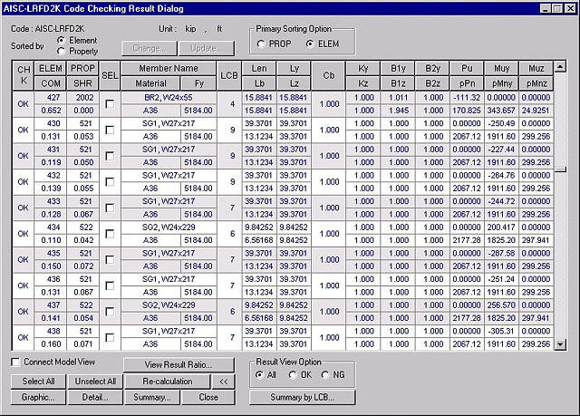
1. AISC-LRFD2K
AISC-LRFD2K Code Checking Result dialog box
The contents are as per AISC-LRFD93.
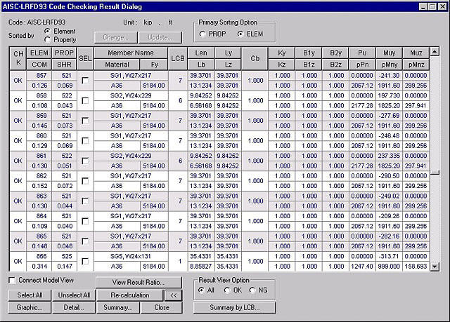
2. AISC-LRFD93
AISC-LRFD93 Code Checking Results dialog box
COM: Maximum combined strength ratio
SHR: Strength ratio for shear force (Required shear strength /Nominal shear strength)
LCB: Load combination number which produces the maximum combined strength ratio
B1y, B1z: Moment magnification factors for moments about the member's strong and weak axes due to vertical load in the steel frame prevented from sidesway
B2y, B2z: Moment magnification factors for moments about the member's strong and weak axes due to horizontal load in the steel frame unprevented from sidesway
Pu: Axial force of member
Muy, Muz: Bending moments about the member's strong and weak axes respectively
phiPn: Nominal axial strength of member
phiMny, phiMnz: Nominal bending strengths about the member's strong and weak axes respectively
Other symbols are defined in AISC-ASD89.
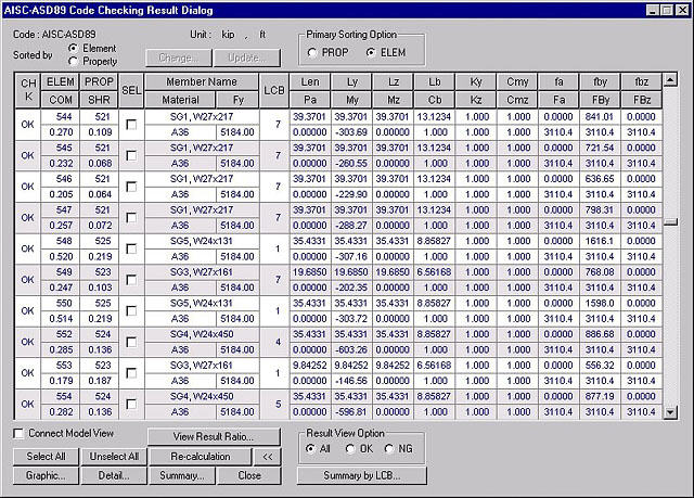
3. AISC-ASD89
AISC-ASD89 Code Checking Results dialog box
CHK: Display the strength verification results by members
= "OK": stress in the member is within the allowable stress range
= "OK*": stress in the member is within the allowable stress range but exceeds the allowable slenderness ratio
= "NG": stress in the member exceeds the allowable stress range
= "NG*": stress in the member exceeds the allowable stress range and slenderness ratio
ELEM: Element number
PROP: Section property number
COM: Maximum Combined Interaction Ratio
SHR: Stress ratio for shear force (Computed shear stress /Allowable shear stress)
SEL: Member selection for sectional change, rechecking and producing results
Member Name: Section designation entered by the user or stored internally by the program
Material: Material designation entered by the user or stored internally by the program
Fy: Yield strength
LCB: Load combination number which produces the maximum combined stress ratio
Len: Member length calculated with respect to node local coordinates of the analysis model
Ly, Lz: Unbraced lengths of the member buckling about strong axis (Local-y) and weak axis (Local-z) respectively
Lb: Laterally unbraced length of the compression flange of the member
Pa: Axial force of the member (Pa > 0: tension, Pa < 0: compression)
My, Mz: Bending moments about the member's strong axis and weak axis respectively
Cb: Bending coefficient for bending moment about the member's strong axis
Ky, Kz: Effective buckling length factors for the member buckling about strong axis and weak axis respectively
Cmy, Cmz: Moment Coefficients for the member's strong and weak axes respectively (Equivalent Moment Correction Factor)
fa: Compressive stress in the member's axial direction
fby, fbz: Bending stresses due to mements about the member's strong and weak axes respectively
Fa: Allowable compressive stress in the member's axial direction (allowable tension stress)
FBy, FBz: Allowable bending stresses about the member's strong axis and weak axis respectively
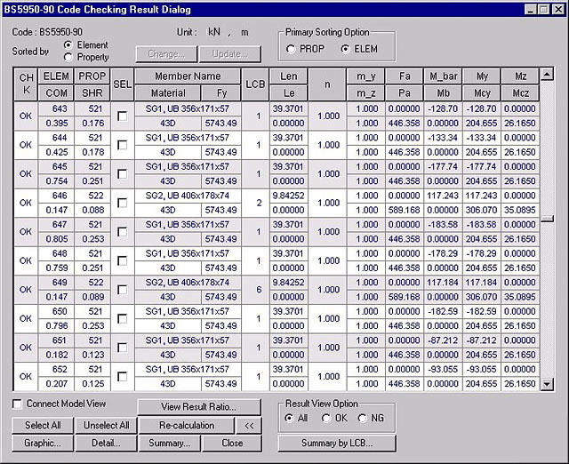
4. BS5950-90
BS5950-90 Checking Results dialog box
Le: Effective buckling length
n: Slenderness correction factor
m_y, m_z: Equvalent uniform moment factors for moments about the member's strong and weak axes respectively
Fa: Applied design axial force
Pa: Axial design strength capacity
M_bar: Equivalent uniform moment
Mb: Buckling resistance moment capacity (lateral torsional)
My: Applied moment about the member's strong axis at critical region
Mcy: Moment capacity of section about the member's strong axis, in the absence of axial load
Mz: Applied moment about the member's weak axis at critical region
Mcz: Moment capacity of section about the member's weak axis, in the absence of axial load
Other symbols are defined in AISC-LRFD93.
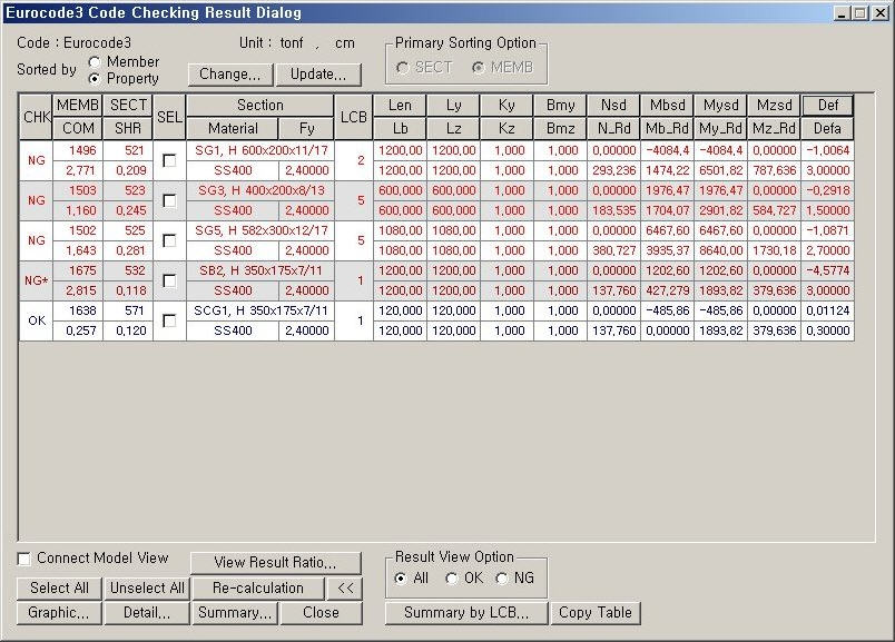
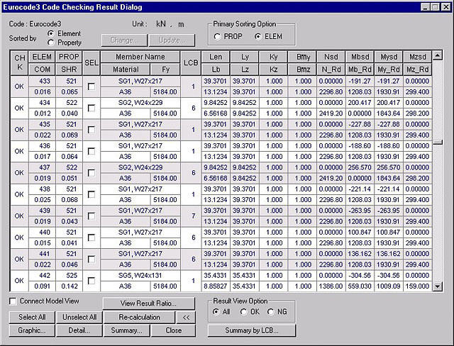
5. Eurocode 3
Eurocode 3 Checking Results dialog box
Bmy, Bmz: equivalent uniform moment factors
Nsd: Applied design axial force
N_Rd: Design axial resistance
Mbsd: Applied design bending moment
Mb_Rd: Design buckling resistance moment of a laterally unrestrained beam
Mysd: Applied design bending moment about the member's strong axis
My_Rd: Design buckling resistance moment about the member's strong axis
Mzsd: Applied design bending moment about the member's weak axis
Mz_Rd: Design buckling resistance moment about the member's weak axis
Other symbols are defined in AISC-LRFD93
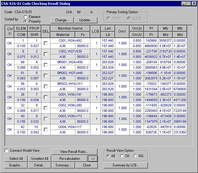
6. CSA-S16-01
CHK: Display the strength verification results by members
= "OK": stress in the member is within the allowable stress range
= "OK*": stress in the member is within the allowable stress range but exceeds the allowable slenderness ratio
= "NG": stress in the member exceeds the allowable stress range
= "NG*": stress in the member exceeds the allowable stress range and slenderness ratio
ELEM: Element number
PROP: Section property number
COM: Maximum Combined Interaction Ratio
SHR: Stress ratio for shear force (Computed shear stress /Allowable shear stress)
SEL: Member selection for sectional change, rechecking and producing results
Member Name: Section designation entered by the user or stored internally by the program
Material: Material designation entered by the user or stored internally by the program
Fy: Yield strength
LCB: Load combination number which produces the maximum combined stress ratio
Len: Member length calculated with respect to node local coordinates of the analysis model
Lb: Laterally unbraced length of the compression flange of the member
Om1: Coefficient used to determine equivalent uniform bending effect in beam columns
Om2y, Om2z: Coefficients to account for increased moment resistance about the member's strong and weak axes respectively of a laterally unsupported beam segment when subject to a moment gradient in each direction
Pf: Axial force
Mfy, Mfz: Bending moments about the member's strong and weak axes respectively in a member or component under factored load
Pr: Axial resistance
Mry, Mrz: Factored moments resistance about the member's strong and weak axes respectively in a member or component
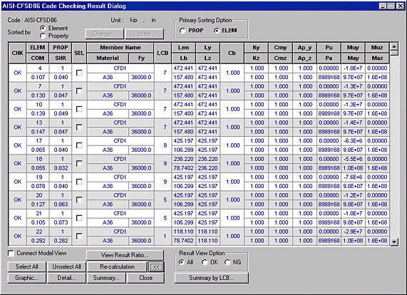
7. AISI-CFSD86
AISI-CFSD86 Code Checking Results dialog box
COM: Maximum combined strength ratio
SHR: Strength ratio for shear force (Required shear strength /Nominal shear strength)
Ap_y, Ap_z: Moment magnification factors for moments about the member's strong and weak axes due to vertical load in steel frames prevented from sidesway
Pu: Axial force of member
Muy, Muz: Bending moments about the member's strong and weak axes respectively
Pa: Allowable axial strength of member
May, Mnaz: Allowable bending strengths about the member's strong and weak axes respectively
Other symbols are defined in AISC-ASD89.
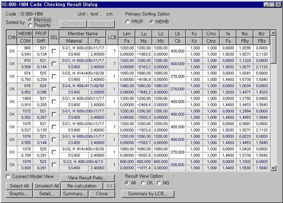
8. IS800-1984
IS800-1984 Code Checking Result dialog box
Cb: Bending coefficient for bending moment about the member's strong axis
Cmy, Cmz: Moment Coefficients for the member's strong and weak axes respectively
Other symbols are defined in AIK-ASD83.
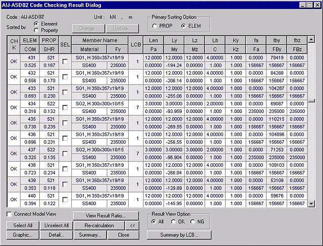
9. AIJ-ASD02 (available upon request)
AIJ-ASD73 Code Checking Result dialog box
The contents are identical to that for AIK-ASD83 except that C replaces Cm.
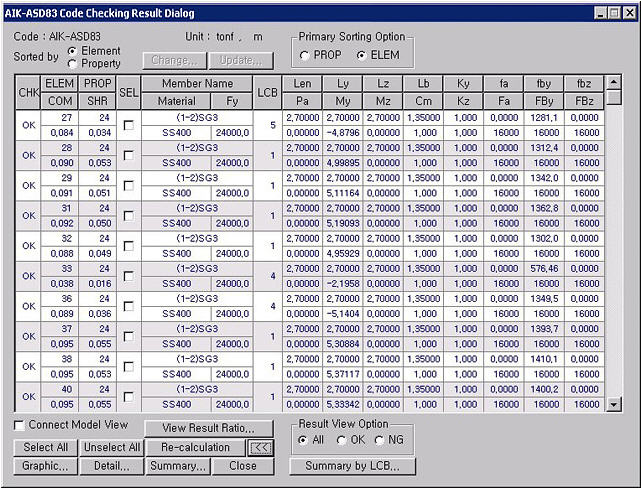
10. AIK-ASD83 (available upon request)
AIK-ASD83 Code Checking Results dialog box
CHK : Display the strength verification results by members
= "OK" : stress in the member is within the allowable stress range
= "OK*" : stress in the member is within the allowable stress range but exceeds the allowable slenderness ratio
= "NG" : stress in the member exceeds the allowable stress range
= "NG*" : stress in the member exceeds the allowable stress range and slenderness ratio
ELEM : Element number
PROP : Section property number
COM : Maximum Combined Stress Ratio
SHR : Stress ratio for shear force (Computed shear stress /Allowable shear stress)
SEL : Member selection for sectional change, rechecking and producing results
Member Name : Section designation entered by the user or stored internally by the program
Material : Material designation entered by the user or stored internally by the program
Fy : Yield strength
LCB : Load combination number which produces the maximum combined stress ratio
Len : Member length calculated with respect to node local coordinates of the analysis model
Ly, Lz : Unbraced lengths of the member buckling about strong axis (Local-y) and weak axis (Local-z) respectively
Lb : Laterally unbraced length of the compression flange of the member
Ky, Kz : Effective buckling length factors for the member buckling about strong axis and weak axis respectively
fa : Compressive stress in the member's axial direction
fby, fbz : Bending stresses due to mements about the member's strong and weak axes respectively
Pa : Axial force of the member (Pa > 0: tension, Pa < 0: compression)
My, Mz : Bending moments about the member's strong axis and weak axis respectively
Cm : Bending coefficient for bending moment about the member's strong axis
Fa : Allowable compressive stress in the member's axial direction (allowable tension stress)
FBy, FBz : Allowable bending stresses about the member's strong axis and weak axis respectively
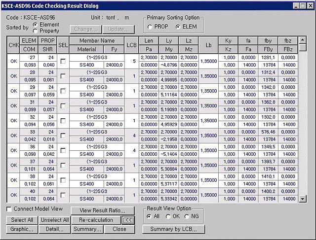
11. KSCE-ASD96 (available upon request)
KSCE-ASD96 Code Checking Results dialog box
The contents are similar to that for AIK-ASD83
12. AIK-LSD97 (available upon request)
AIK-LSD97 Code Checking Results dialog box
Cb: Bending coefficient for bending moment about the member's strong axis
B1y, B1z: Moment magnification factors for moments about the member's strong and weak axes due to vertical load in the steel frame prevented from sidesway
B2y, B2z: Moment magnification factors for moments about the member's strong and weak axes due to horizontal load in the steel frame unprevented from sidesway
Pu: Axial force of member
Muy, Muz: Bending moments about the member's strong and weak axes respectively
phiPn: Nominal axial strength of member
phiMny, phiMnz: Nominal bending strengths about the member's strong and weak axes respectively
COM: Maximum combined strength ratio
SHR: Strength ratio for shear force (Required shear strength /Nominal shear strength)
LCB: Load combination number which produces the maximum combined strength ratio
Other symbols are defined in AIK-ASD83.
13. AIK-CFSD98 (available upon request)
AIK-CFSD98 Code Checking Results dialog box
Refer to AISI-CFSD86
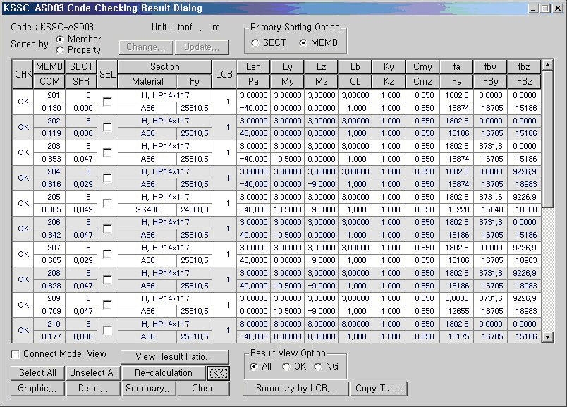
14. KSSC-ASD03
AIK-ASD83 Code Checking Result dialog box
CHK: Display the strength verification results by members
= "OK": stress in the member is within the allowable stress range
= "OK*": stress in the member is within the allowable stress range but exceeds the allowable slenderness ratio
= "NG": stress in the member exceeds the allowable stress range
= "NG*": stress in the member exceeds the allowable stress range and slenderness ratio
MEMB: member number
PROP: Section property number
COM: Maximum Combined Interaction Ratio
SHR: Stress ratio for shear force (Computed shear stress /Allowable shear stress)
SEL: Member selection for sectional change, rechecking and producing results
Note
Member Name: Section designation entered by the user or stored internally by the program
Material: Material designation entered by the user or stored internally by the program
Fy: Yield strength
LCB: Load combination number which produces the maximum combined stress ratio
Len: Member length calculated with respect to node local coordinates of the analysis model
Ly, Lz: Unbraced lengths of the member buckling about the strong axis (Local-y) and the weak axis (Local-z) respectively
Lb: Laterally unbraced length of the compression flange of the member
Ky, Kz: Effective buckling length factors for the member buckling about the strong and the weak axes respectively
fa: Compressive stress in the member's axial direction
fby, fbz: Bending stresses due to moments about the member's strong and weak axes respectively
Pa: Axial force of the member (Pa > 0: tension, Pa < 0: compression)
My, Mz: Bending moments about the member's strong and weak axes respectively
Cm: Bending coefficient of the bending moment about the member's strong axis
Fa: Allowable compressive stress in the member's axial direction (allowable tension stress)
FBy, FBz: Allowable bending stresses about the member's strong and weak axes respectively
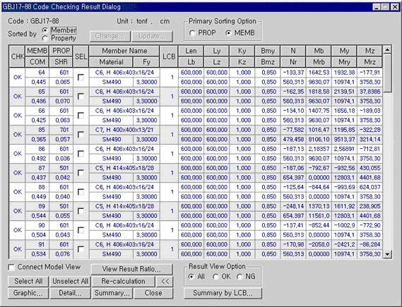
15. GBJ17-88
GBJ17-88 Code Checking Result dialog box
CHK: Display the strength verification results by members
= "OK": stress in the member is within the allowable stress range
= "OK*": stress in the member is within the allowable stress range but exceeds the allowable slenderness ratio
= "NG": stress in the member exceeds the allowable stress range
= "NG*": stress in the member exceeds the allowable stress range and slenderness ratio
MEMB: member number
PROP: Section property number
COM: Maximum Combined Interaction Ratio
SHR: Stress ratio for shear force (Computed shear stress /Allowable shear stress)
SEL: Member selection for sectional change, rechecking and producing results
Member Name: Section designation entered by the user or stored internally by the program
Material: Material designation entered by the user or stored internally by the program
Fy: Yield strength
LCB: Load combination number which produces the maximum combined stress ratio
Len: Member length calculated with respect to node local coordinates of the analysis model
Ly, Lz: Unbraced lengths of the member buckling about the strong axis (Local-y) and the weak axis (Local-z) respectively
Lb: Laterally unbraced length of the compression flange of the member
Ky, Kz: Effective buckling length factors for the member buckling about the strong and the weak axes respectively
Bmy, Bmz: Moment Coefficients for the member's strong and weak axes respectively
N: Applied design axial force
Nr: Design axial resistance
Mb: Equivalent uniform moment
Mrb: Buckling resistance moment capacity
My: Applied moment about the member's strong axis
Mry: Moment capacity of the section about the member's strong axis
Mz: Applied moment about the member's weak axis
Mrz: Moment capacity of the section about the member's weak axis
Common Control
Display the strength verification results for the maximum combined stress ratios (combined strength ratios) by elements or properties.
Sorting by Property displays the strength verification results of the element producing the maximum combined stress ratio (combined strength ratio) among the members of the same property.
Once Property is selected, SEL controls all the elements of the same properties.
When the strength verification results that accompany the maximum combined stresses (strength) are to be produced by elements, the results are sorted by section numbers or element numbers in an ascending order.
Redesign the selected members.
When the redesign is executed from the results displayed by section properties all the elements attributed to the same sections are included.
Check in the option to select and highlight the selected members in Model View.
When the results are sorted by properties, the member design results are produced for the member with the maximum combined stress (strength).
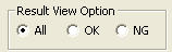
All: Produce all the strength verification results in the Checking Results dialog box
OK: From the strength verification results, display only the design results that have met the design requirements (OK) in the Checking Results dialog box
NG: From the strength verification results, display only the design results that have not satisfied the design requirements (NG) in the Checking Results dialog box
Produce strength verification results for all the load combinations for the selected members.
Section change
Member Name: Section name internally stored by the program
CHK: Display the strength verification results by sections
= "OK": Stress (required strength) of the section is within the allowable stress range (design strength)
= "NG": Stress (required strength) of the section exceeds the allowable stress range (design strength)
SEL: Select the sections to be changed.
LCB: Load combination number which produces the maximum combined stress ratio (combined strength ratio)
COM: Maximum Combined Stress Ratio (combined strength ratio)
SHR: Stress ratio (strength ratio) for shear force = shear stress/Allowable shear stress (Required shear strength/Design shear strength)
H: Height of the section
B: Width of the section
Area: Area of the section
(The MGB file containing section data saved by the user can be used ; only DB/User Section is included in the DB construction)
Specify the range of sectional dimensions within which the section is to be changed.
Select the Checkbox if the range of the section dimensions is to be partially identical to the current section in use. To specify the range, enter the dimensions corresponding to the units used in From and To.
Enter the dimensions only in the From fields when the new section is pre-defined with known dimensions.
(.GD1) and close the dialog box.
Update Changed Properties
Properties Before Change represents the sectional properties used in the analysis.
Properties After Change represents the changed sectional properties subsequent to performing the final strength verification.
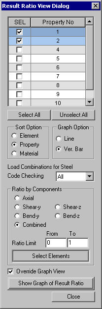
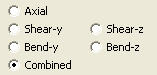
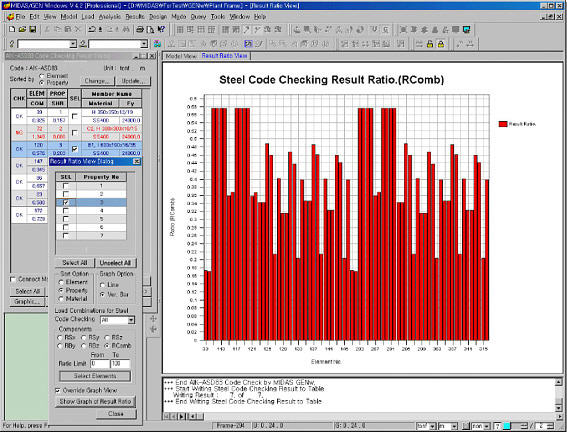
Plot strength verification results in graphs
Plot the graphs for strength verification results by materials, sections and members.
Select the sorting option for graphic output. (Define a table output reference for SEL selection)
Select a graphic output option. (Select Line or Vertical Bar)
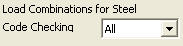
Specify the load combination for graphic output (All signifies the load combination which produces the maximum ratio among all the load combinations)
Select elements satisfying Sorting Option, Load Combinations for Steel Code Checking, Ratio and Ratio Limit in Model View.
Check in the box to produce the graph on the existing View. (If unchecked, a new View is selected)
Produce the strength verification result ratios on a graph for members satisfying the selected conditions
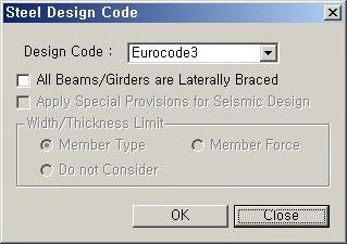
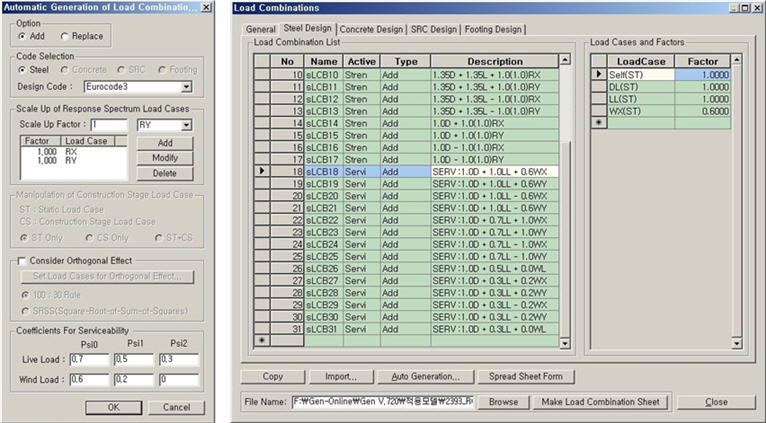
1. Select the design code: Eurocode 3
2. Generate load combinations as per Eurocode2
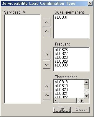
3. Assign/Confirm Serviceability Load Combination Type
Design > General Design Parameter > Serviceability Load Combination Type
4. Enter Serviceability parameters
Design > Steel Design Parameter > Serviceability Parameters
5. Check Result Dialog: Review the deflection limit checking results in the last column of the Result Dialog.
Design > Steel Code Checking
[Notation]
6. Check Graphic Results
Serviceability checking results will be produced under the "Deflection Checking Result" at the bottom of the Graphic Report.
7. Check Detail Results
Serviceability checking results (i.e., deflection checking results) will be produced in the Detail Report.
| |||||
|
|


 : Display the applicable
code for strength verification.
: Display the applicable
code for strength verification.
 : Display the unit system
selected by the user.
: Display the unit system
selected by the user.
 : Select all the members
 : Cancel the selection of
all the members
: Cancel the selection of
all the members
 : Display detail strength
verification results
: Display detail strength
verification results : Display simplified
strength verification results
: Display simplified
strength verification results : Produce the strength
verification results in the form of summary calculations for the selected
members.
: Produce the strength
verification results in the form of summary calculations for the selected
members.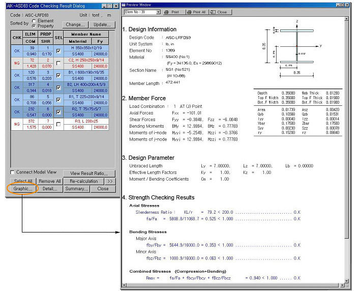
 : Produce the strength
verification results in the form of detail calculations for the selected
members.
: Produce the strength
verification results in the form of detail calculations for the selected
members.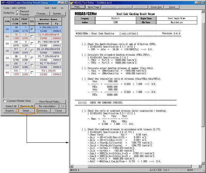
 : Produce a summary
list of strength verification results for the selected members.
: Produce a summary
list of strength verification results for the selected members.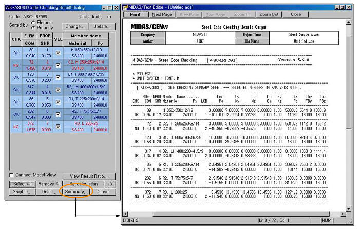
 : Close the dialog box
 : Propose sections satisfying
the selected element conditions.
: Propose sections satisfying
the selected element conditions.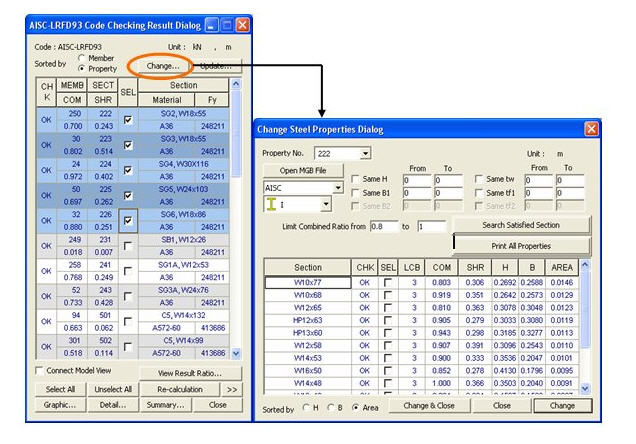
 : Select the property
number to be changed
: Select the property
number to be changed : Open an MGB file to
be used as the section DB
: Open an MGB file to
be used as the section DB : Select a DB for the
change of sections
: Select a DB for the
change of sections : Select a section shape
to which the section is to be changed
: Select a section shape
to which the section is to be changed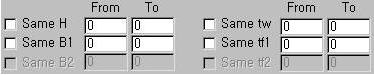
 : Specify the range
of combined stress ratios (combined strength ratios) for the section to
be changed.
: Specify the range
of combined stress ratios (combined strength ratios) for the section to
be changed. : Verify strength and
produce results for the section satisfying the design conditions.
: Verify strength and
produce results for the section satisfying the design conditions. : Prints all section properties
that satisfy the design conditions in a text format.
: Prints all section properties
that satisfy the design conditions in a text format.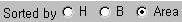 : Select the sorting
preference for section strength verification results.
: Select the sorting
preference for section strength verification results. : Verify the strength
of the selected section, save the changed results in the steel strength
verification file
: Verify the strength
of the selected section, save the changed results in the steel strength
verification file  : Update the modeling
properties with the changed sections after performing strength verification.
: Update the modeling
properties with the changed sections after performing strength verification.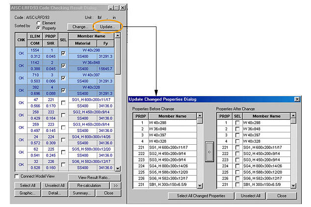
 : Auto-select only the
changed properties.
: Auto-select only the
changed properties. : Update the properties in
the model with the selected sections.
: Update the properties in
the model with the selected sections.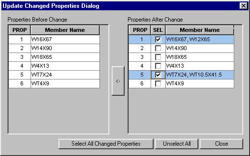


 : Select a ratio type
for output
: Select a ratio type
for output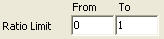 : Enter the ratio range
for output
: Enter the ratio range
for output

 Procedure for Serviceability
Check as per Eurocode 3
Procedure for Serviceability
Check as per Eurocode 3