Graphic Editor
| ||||||||||||||||||||||||||||||||||||||||||
|
| ||||||||||||||||||||||||||||||||||||||||||
|
| ||||||||||||||||||||||||||||||||||||||||||
|
MIDAS Graphic Editor linked to MIDAS Family Program is a vector-based graphic editor, which is readily used to edit and print various types of Graphic files. Graphic Editor can freely add or edit all types of statements in BMP or EMF (enhanced metafile) files created by MIDAS/Gen. It enables the user to prepare refined presentation documents. In addition, Graphic Editor can be used analogous to the drawing functions of MS-PowerPoint and Word.
Drawing
- Straight line
- Select | ||||||||||||||||||||||||||||||||||||||||||
|
| ||||||||||||||||||||||||||||||||||||||||||
|
| ||||||||||||||||||||||||||||||||||||||||||
|
| ||||||||||||||||||||||||||||||||||||||||||
|
From the Main Menu select Tools > Graphic Editor.
Shortcut key : [Ctrl]+[F6]
Windows Menu :
Execute | ||||||||||||||||||||||||||||||||||||||||||
|
| ||||||||||||||||||||||||||||||||||||||||||
|
| ||||||||||||||||||||||||||||||||||||||||||
|
.jpg)
|
Function |
Directions |
|
Draw Straight Line |
Click |
|
Draw Continuous Poly Line |
Click |
|
Draw Polygon |
Click |
|
Draw Rectangle |
Click |
|
Draw Continuous Poly Curve |
Click |
|
Draw Closed Curve |
Click |
|
Draw Ellipse |
Click |
|
Insert Text |
Click |
|
Insert Image |
Click |
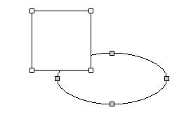
 Draw Line. Then,
left-click the start point and drag the mouse to the desired position.
Draw Line. Then,
left-click the start point and drag the mouse to the desired position. Draw Poly line. Then,
click consecutively the points to draw connecting lines. Double-click
the last point to finish. If the mouse is right-clicked along the way,
the drawing will be cancelled.
Draw Poly line. Then,
click consecutively the points to draw connecting lines. Double-click
the last point to finish. If the mouse is right-clicked along the way,
the drawing will be cancelled. Draw Polygon. Then,
click the corners of the polygon and double-click the last point to finish.
If the mouse is right-clicked along the way, the drawing will be cancelled.
Draw Polygon. Then,
click the corners of the polygon and double-click the last point to finish.
If the mouse is right-clicked along the way, the drawing will be cancelled. Draw Rectangle. Then,
click the top-left corner of the rectangle and drag the mouse to the bottom-right
corner.
Draw Rectangle. Then,
click the top-left corner of the rectangle and drag the mouse to the bottom-right
corner. Draw Poly Curve.
Then, click the control points of the curve and double-click the last
point. A single curve is formed by the end points, which passes through
two intermediate control points. If the mouse is right-clicked along the
way, the drawing will be cancelled.
Draw Poly Curve.
Then, click the control points of the curve and double-click the last
point. A single curve is formed by the end points, which passes through
two intermediate control points. If the mouse is right-clicked along the
way, the drawing will be cancelled. Draw Closed Curve.
Then, click the control points of the closed curve and double-click the
last point. A single curve is formed by the end points, which passes through
two intermediate control points. If the mouse is right-clicked along the
way, the drawing will be cancelled. The surface of the closed curve can
be filled in with a desired color.
Draw Closed Curve.
Then, click the control points of the closed curve and double-click the
last point. A single curve is formed by the end points, which passes through
two intermediate control points. If the mouse is right-clicked along the
way, the drawing will be cancelled. The surface of the closed curve can
be filled in with a desired color. Draw Ellipse. Then,
click the top-left corner of the rectangle on the circumference of the
ellipse and drag the mouse to the bottom-right corner.
Draw Ellipse. Then,
click the top-left corner of the rectangle on the circumference of the
ellipse and drag the mouse to the bottom-right corner. Insert Text. Then,
click the desired position with the mouse. "TEXT" character
appears. Double-click the character and type in the text. Right-click
the mouse and select [Properties...] from the menu to setup the font and
borders.
Insert Text. Then,
click the desired position with the mouse. "TEXT" character
appears. Double-click the character and type in the text. Right-click
the mouse and select [Properties...] from the menu to setup the font and
borders. Insert Image. Then
the Open File dialog box appears. Select the image file and click the
insert position. Once the image is inserted, the size and position can
be adjusted.
Insert Image. Then
the Open File dialog box appears. Select the image file and click the
insert position. Once the image is inserted, the size and position can
be adjusted.
Note
When a particular element is to be drawn to the same proportion or orthogonally,
hold down [Shift] and draw the element.
 Editing
Select
Graphic Editor is basically in a Select mode. Click  to switch
to the Select mode if not already in the mode. In the Select mode, click
the object to select. When several objects are to be selected, left-click
and drag the mouse. Or, hold down [Ctrl] and click each object. The last
selected object becomes the 'reference' object and is distinguished by
gray selection handles. The 'reference' object is used as reference for
the Align functions. If the 'reference' object is to be changed, hold
down [Ctrl] and click the new reference object. If a particular object
is not to be selected among several objects, press [Shift] and click the
relevant object.
to switch
to the Select mode if not already in the mode. In the Select mode, click
the object to select. When several objects are to be selected, left-click
and drag the mouse. Or, hold down [Ctrl] and click each object. The last
selected object becomes the 'reference' object and is distinguished by
gray selection handles. The 'reference' object is used as reference for
the Align functions. If the 'reference' object is to be changed, hold
down [Ctrl] and click the new reference object. If a particular object
is not to be selected among several objects, press [Shift] and click the
relevant object.
Move
If the cursor is moved to the center part of the object selected in the
Select mode, the cursor switches to the Move mode  . At this
time, left-click and drag the mouse to move the object to a desired position.
If the Grid Snap option is active, the motion follows the snapped grids.
. At this
time, left-click and drag the mouse to move the object to a desired position.
If the Grid Snap option is active, the motion follows the snapped grids.
If an object is to be moved precisely, it may be effective to use the motion icons. Clicking a relevant icon once moves the object by 1 unit. Clicking an icon while holding down [Shift] moves the object by 5 units.

Align
Objects can be easily arranged by the Align functions. If several objects
are selected, the 'reference' object with gray handles becomes the aligning
reference.
|
|
Align relative to top |
|
|
Align relative to horizontal center |
|
|
Align relative to bottom |
|
|
Align relative to left |
|
|
Align relative to vertical center |
|
|
Align relative to right |


The regular spacing icons arrange the selected objects at a regular spacing.
|
|
Equal horizontal spacing |
|
|
Equal vertical spacing |


The Size Align icons fit all the selected objects to identical dimensions. If several objects are selected, the 'reference' object with gray handles becomes the fitting reference.
|
|
Fit horizontal size |
|
|
Fit vertical size |
|
|
Fit horizontal / vertical sizes |


Rotate
Click the Rotate icons to rotate selected object(s).
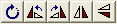
The Rotate icons feature "Free Rotation", "Rotate 90° to left", "Rotate 90° to right", "Horizontally Symmetric Rotation" and "Vertically Symmetric Rotation" functions. When "Free Rotation" is to be selected, move the cursor to the selected object then the cursor transforms into an icon. At this time, keep the mouse left-clicked and move the mouse to freely rotate the object(s).
Change Size
To find out if the size of the selected object can be changed, place the
pointer on a handle of the object then the pointer will transform into
a double-arrow signaling that the size of the object can be changed. The
size can be changed left/rightward, vertically or left/right/vertically
depending on the selected handle.
Grouping/Ungrouping
Select several objects and click  (Grouping) to combine
the selected objects into one object.
(Grouping) to combine
the selected objects into one object.
When the grouping is to be released, click
 (Ungrouping). Based on the order of Grouping, Ungrouping
starts one-by-one from the last Grouping in a reverse order.
(Ungrouping). Based on the order of Grouping, Ungrouping
starts one-by-one from the last Grouping in a reverse order.
Grouping/Ungrouping can also be accessed from the Context Menu displayed by right-clicking the mouse on the object(s).
Stacking
Order
Overlapping objects are displayed in a particular stacking order, called
Z-order. The object with the highest order positions itself at the top
of stack. Lower order objects are underlain by higher order objects. This
order is basically established by the order in which the objects were
created. To change the order, select the objects and click the Stacking
Order icons.

The Stacking Order functions are "To the top", "To the bottom", "One-step forward" and "One-step backward". Stacking Order can also be accessed from the Context Menu displayed by right-clicking the mouse on the object.
Point Edit
Click  Point Edit to switch to the Point Edit mode. Each
handle moves to the points constituting the object.
Point Edit to switch to the Point Edit mode. Each
handle moves to the points constituting the object.
Point Move
In the Point Edit mode, move the mouse to a handle then the cursor shape
transforms to signal that motion is allowed. Left-click and drag the mouse
to move the point constituting the object.
Point Insert
If [Ctrl] is pressed with the cursor between the points, the cursor transforms
into the Insert state. Then, left-click the mouse to insert a point. This
is applicable only for objects, which can be constituted by an unlimited
number of points, such as a curve and a continuous line.
Point Delete
If [Ctrl] is pressed on a point, the cursor transforms into an 'X'-shape
signaling the Delete state, then left-click the mouse to delete the point.
This is applicable only for objects, which can be constituted by an unlimited
number of points, such as a curve and a continuous line.
Change Component
Properties
Select the object for which properties are to be changed and click  (Change Component Properties). Or, right-click on the object
and select [Properties...] in the context menu to display the Change Component
Properties dialog box. Then, setup the detailed properties related to
the object. The displayed properties (color and width of line, color of
surface, etc.) can then be selected or changed.
(Change Component Properties). Or, right-click on the object
and select [Properties...] in the context menu to display the Change Component
Properties dialog box. Then, setup the detailed properties related to
the object. The displayed properties (color and width of line, color of
surface, etc.) can then be selected or changed.
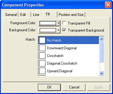
Change Component Properties dialog box
Other Functions
Undo/Redo
Undo/Redo restores / re-executes one-by-one from the most recent change
in Graphic Editor.
Grid View and Grid Snap

Click the Grid View icon to display or hide the grid. Click Grid Snap to snap all the created nodes to contiguous grid points.
Zoom, Fit to Window, Fit to Range

Zoom
Click Zoom to magnify a part of the window. When the cursor transforms
into a magnifying glass, left-click to magnify the drawing by a certain
proportion. If an area is assigned by left-clicking and dragging the mouse,
the area is magnified to fit the window.
Fit to
Window
Magnify/reduce all the current objects in the window so that they are viewed
as large as possible without being cut.
Fit to
Range
Magnify/reduce the currently selected objects so that they are viewed as
large as possible without being cut.
Functions related to File
 New
New
Create a new blank drawing.
 Open
Open
Open a drawing file. MGF (MIDAS Graphic Format), BMP and EMF formats can
be opened.
 Save
Save
Save the created drawing in a file. The formats that can be saved are MGF
(MIDAS Graphic Format), BMP, EMF.
Printer
Setup
Setup the printer, margins, type and direction of document etc.
Print Preview
Preview the printing form prior to hard-printing.
 Print
Print
Hard-print the drawing.