Preferences
|
|
|
|
|
|
Set all types of initial preferences for general operation of MIDAS/Gen.
The preferences set by the command are listed below. Use the Tree Menu located to the left of the dialog box to check or modify the defaults.
Environment
General: Provide the user's name, company logo, directory for temporary files and temporary file saving requirements
View: Defaults for the working window
Tolerance Data: Tolerance assignment for merging nodes or intersecting elements
Property: Data Base assignment for material properties and member properties
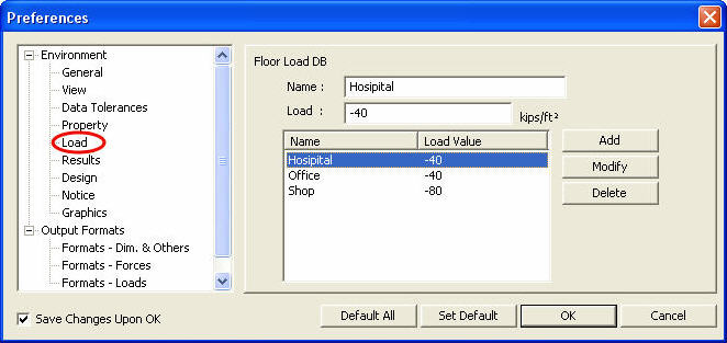
Load: Predefine the magnitudes of floor loads in the database.
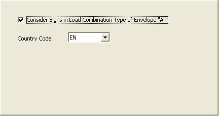
Results: When the method of load combination is Envelope, output the signs of analysis results.
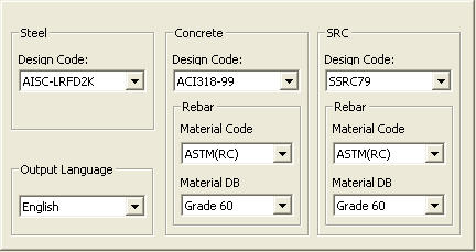
Design: Assign applicable design standards for different material types and material properties for structural steel
Notice: Check the latest news uploaded on the MIDAS User website.
Graphics: Specify the Printout option.
Output Formats
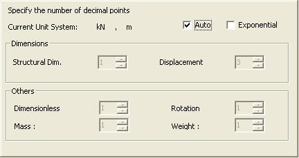
Formats - Dim. & Others: Assignment of format for numerical values to be used for producing model data and analysis results
Formats - Forces |
|
|
|
|
|
|
|
From the Main Menu select Tools > Preferences. |
|
|
|
|
|
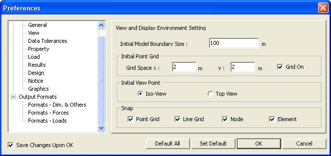
Display the following Preferences dialog box:
Preferences dialog box
Select the items in the Tree Menu to the left of the dialog box to display the corresponding features to the right. Check Save
Changes Upon OK and click
Default All: Set all the preferences Settings as default.
Set Default: Set the current preferences Setting as default.
Details Setting
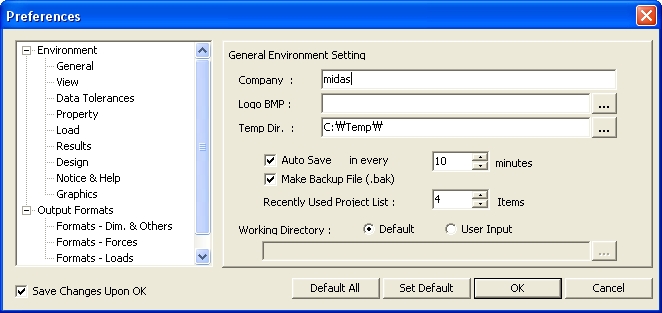
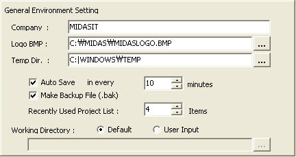
General Environment Setting dialog box
Company: User's name
Logo BMP: Specify a file containing the company logo that will be printed in various analysis/design results.
Temp Dir: Assign a directory in which temporary files are created and deleted during the execution of MIDAS/Gen.
Note
Auto Save: Auto-save the project file at a given time-interval.
Make Backup File (.bak): Save a backup file (.bak) whenever the file is changed and saved.
Recently Used Project List: List the prescribed number of files recently used at the bottom of the File Menu
Working Directory: Display the directory when opening and closing a file. Set the default working window when creating a new project file or opening an existing file.
View and Display Environment Setting dialog box
Initial Model Boundary Size: Assign the size of the default window when creating a new project
Initial Point Grid Grid Space
X: Point Grid spacing in UCS x-direction when creating a new project.
It can be temporarily modified using Grid Space
Y: Point Grid spacing in UCS y-direction when creating a new project.
It can be temporarily modified using
Grid on: Check in the option to display the Point Grid on the screen when creating a new project file or opening an existing file (refer to "Grids").
Initial View Point Check in the option to display the model window in ISO View or Top View when creating a new project file or opening an existing file (refer to "View Point").
Snap Check in the option to activate Snap for Point Grid, Line Grid, Node and Element when creating a new project file or opening an existing file (refer to "Snap").
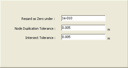
Data Tolerances dialog box
Regard as Zero under Treat the values less than the specified as "0"
Node Duplication Tolerance Specify a tolerance for merging more than one node into a single node. The tolerance is applicable when combining or copying nodes.
Intersect Tolerance Specify an intersect tolerance for merging contiguous nodes and elements or between elements when executing Intersect.
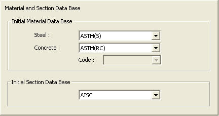
Specify data bases for material and section properties.
Material and Section Data Base dialog boxThe floor loads predefined in the database can be recalled from Load >Define Floor Load Type.
Floor Load DB dialog box
Define Floor Load Type dialog box
Environment > Results
Result dialog box
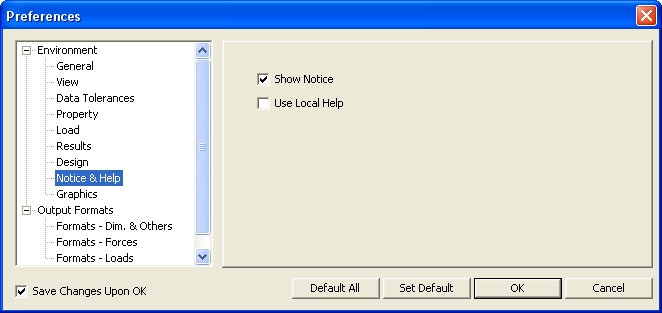
Design dialog boxRevision of V.7.6.1 Show Notice : When MIDAS/Gen is executed, the latest program upgrade information on the homepage of MIDASoft, Inc can be checked.
Use Local Help : Check on to use the Local Help (MidasGen.chm) as a default manual. If this option is checked off, the web-based online manual is invoked.
Notice dialog box
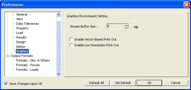
Graphics Environment Setting Specify the Buffer Size for graphic display.
Enable Vector-Based Print Out It may take time to print out if Open-GL that the program uses as default is used. Select this option to use the Vector-Based Engine of low resolution to reduce time for printout.
Enable Low Resolution Print Out Select this option to optimize the background when the Vector-Based Print Out option is enabled.
Graphics dialog boxOutput Formats > Formats - Dim & Others
Formats (Dim & Others) dialog box
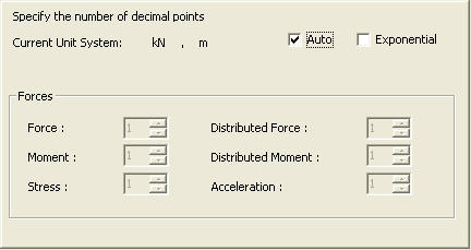
Specify the number of decimal points when producing analysis results.
If Auto is checked in, the number of decimal points for each numerical value is auto-fitted by the program according to the pre-defined format as per the selected unit system. If Auto is unchecked, the user may specify the number of decimal points for each item.
If Exponential is checked in, the specified numbers of decimal points are ignored and all the numerical values are produced in exponentials.
Output Formats > Formats - Forces
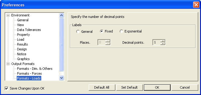
Formats (Forces) dialog boxOutput Formats > Formats - Loads Specify an output format for displaying loads.
Formats (Loads) dialog box
General: The number of significant digits
Fixed: The number of decimal places
Exponential: The number of decimal places of load values to be displayed in exponential
|
|
|
 to immediately effect
the current settings and save the changes in Window Registry for subsequent
uses of MIDAS/Gen.
 Set Point Grid.
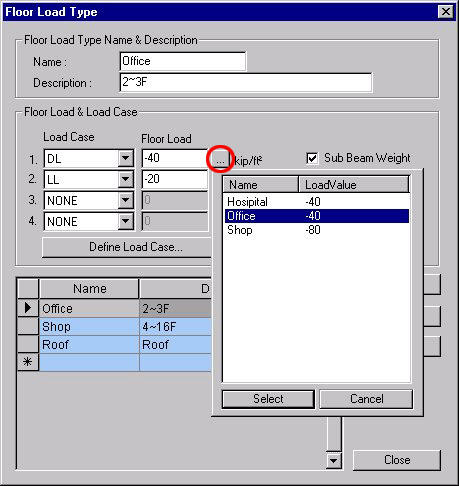
 : Enter the loads per unit
area using the floor loads predefined in Tools>Preferences- Load.
 : If the method of load combination
of analysis results is Envelope, and this option is selected, the values
in "