From the Main
Menu select Model > Elements > Create Elements.
Select Geometry
> Elements > Create in the Menu tab of the Tree Menu.
Click Create Elements in the Icon Menu.
Shortcut key:
[Alt]+1
Click
to the right of Create
Elements: Display the Element Table
Start Node Number
Assign a number to the new starting node
created together with new elements in the Model Window. This number is
auto-set to the largest node number in use +1. To modify this item, click
and select an option to specify a desired number.
Start Element Number
Assign a new starting element number. This
number is auto-set to the largest element number in use +1. To modify
this item, click and select an option to specify a desired
number.
Element Type
Assign an element type and enter additional
data.
Truss:
Truss Element
Tension-only/Hook/Cable:
Tension-only Elements
Truss
Allow.
Comp : Allowable maximum compressive force
Tens. Limit
: Allowable tensile force used in the process of iterative analysis
For tension-only elements, Allow Comp. is
assigned 0 and Tens. Limit is checked off generally. If Tens. Limit is
checked on and a specific value is entered, the element no longer resists
forces exceeding the Tens.
Limit, and the excess forces will be transferred
to neighboring elements.
Hook
If a displacement takes place beyond the
Hook Distance, the element starts resisting tension
Cable
Enter the ratio of unstrained length of
unstrained length to element length (Lu/L) and the Pretension load additionally.
"Cable Element" is auto-converted
into equivalent Truss Element in the case of a linear analysis and Elastic
Catenary Element in the case of a geometric nonlinear analysis.
Generate a Cable Element and introduce Tension
Force at the same time.
Lu:
Enter the unstrained length of Cable (Lu), which will indirectly adjust
element stiffness and tension force from element length. (Lu: Unstrained
length of Cable, L: Element length)
If Lu/L>1, the cable is sagging and reduced
stiffness is applied. If Lu/L<1, the distance between the two nodes
is longer than the unstrained length, and it has an effect of introducing
a tension force.
Pretension:
Enter the Pretension load to be introduced to Cable.
Horizontal:
Enter the Horizontal pretension load, which will be automatically converted
into the pretension load to be introduced to Cable.
Entered pretension is applied only when
nonlinear analysis is performed. Unless geometric nonlinear analysis is
performed, the entered pretension will be ignored. For linear analysis,
pretension should be entered using Load>Prestress Loads> Pretension Loads.
Compression-only/Gap:
Compression-only Elements
Compression-only Truss
Allow.
Tens : Allowable maximum tensile force
Comp. Limit
: Allowable compressive force used in the process of
iterative analysis
For compression-only elements, Allow Tens.
is assigned 0 and Comp. Limit is checked off generally. If Comp. Limit
is checked on and a specific value is entered, the element no longer resists
forces exceeding the Comp. Limit, and the excess forces will be transferred
to neighboring elements.
Gap
If a displacement takes place beyond the
Gap Distance, the element starts resisting compression.
These elements are generally used for modeling
members that exert axial forces only such as space trusses, cables and
diagonal members as well as for modeling contact surfaces.
For example, truss elements resisting axial
tension and compression forces can be used to model a truss structure.
Tension-only elements are suitable for modeling cables whose sagging effects
can be neglected and for modeling diagonal members that are incapable
of transmitting compression forces due to their large slenderness ratios,
such as wind bracings. Compression-only elements can be used to model
contact surfaces between adjacent structural members and to model ground
support conditions taking into account the fact that tension forces cannot
be resisted. Pretension loads can be used when members are prestressed.
Because
these elements do not retain rotational degrees of freedom at nodes, Singular
Errors can occur during the analysis at nodes where they are connected
to the same type of elements or to elements without rotational d.o.f.
MIDAS/Gen prevents such singular errors by restraining the rotational
d.o.f. at the corresponding nodes.
If they are connected to beam elements
that have rotational degrees of freedom, this restraining process is not
necessary.
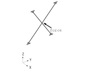
As shown in <Figure 1>, you should
exercise caution not to induce unstable structures when only truss elements
are connected. The structure shown in <Figure 1> (a) lacks rotational
stiffness while being subjected to an external load in its plane, resulting
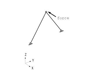
in an unstable condition. <Figure 1> (b) and (c) illustrate unstable
structures in the loading direction (X-Z plane), even though the structures
are stable in the Y-Z plane direction.
You should use tension-only and compression-only
elements with care. Element stiffness may be ignored in the analysis depending
on the magnitudes of loads; e.g., when compression loads are applied to
tension-only elements.
(a) When a force is applied in the X-direction on the
X-Z plane
(b) When a force is applied in the X-direction perpendicular
to the Y-Z plane
(c) When a force is applied in the X-direction perpendicular
to the Y-Z plane
<Figure 1> Typical examples of unstable structures
that are composed of truss (tension only & compression only) elements
Note This element is typically used for modeling prismatic and non-prismatic
tapered structural members that are relatively long compared to section
dimensions. The element can be also used as load-transfer elements connecting
other elements having differing numbers of d.o.f.
In-span concentrated loads, distributed loads,
temperature gradient loads and prestress loads can be applied to beam
elements.
A beam element has 6 d.o.f. per node reflecting
axial, shear, bending and torsional stiffness. When shear areas are omitted,
the corresponding shear deformations of the beam element are ignored.
The beam element is formulated on the basis
of the Timoshenko beam theory (a plane section initially normal to the
neutral axis of the beam remains plane but not necessarily normal to the
neutral axis in the deformed state) reflecting shear deformations. If
the ratio of the section depth to length is greater than 1/5, a fine mesh
modeling is desirable because the effect of shear deformations becomes
significant.
The torsional resistance of a beam element
differs from the sectional polar moment of inertia (they are the same
for circular and cylindrical sections). You are cautioned when the effect
of torsional deformation is large, as the torsional resistance is generally
determined by experimental methods.
Beam and truss elements are idealized line
elements, thus their cross-sections are assumed to be dimensionless. The
cross-sectional properties of an element are concentrated at the neutral
axis that connects the end nodes. As a result, the effects of panel zones
between members (regions where columns and beams merge) and the effects
of non-alignment of neutral axes are not considered. In order for those
nodal effects to be considered, the beam end offset option or geometric
constraints must be used.
The tapered section may be used when the section
of a member is non-prismatic. It may be desirable to use a number of beam
elements to model a curved beam.
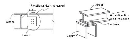
When members are connected by pins or slotted
holes (<Figure 2> (a) and (b)), the Beam End Release option is used.
Note that a singularity error can result in
a case where a particular degree of freedom is released for all the elements
joining at a node, resulting in zero stiffness associated with that degree
of freedom. If it is inevitable, a spring element (or an elastic boundary
element) having a minor stiffness must be added to the corresponding d.o.f.
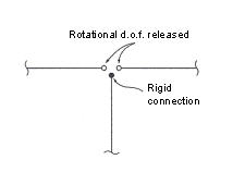
(a) Pin connection (b)
Slot-hole connection
(c) When multiple beam elements are pin connected at a
node
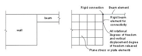
(d)
When
elements having different d.o.f. are connected
<Figure 2> Examples of end-release application
Plate:
Plate Element
Thick:
Thick plate element
Thin:
Thin plate element
With
Drilling DOF: To consider the degree of freedom about the perpendicular
direction to the plate
Note
1 Thick and Thin plates are distinguished by whether or not shear deformation
is considered. Refer to "Important Aspects of Element Selection" of Analysis
Manual.
Note
2 This element can be used to model the structures in which both in-plane
and out-of-plane bending deformations are permitted to take place, such
as pressure vessels, retaining walls, bridge decks, building floors and
mat foundations
Pressure loads can be applied to the surfaces
of the elements in either the GCS or ECS.
A plate element can be either quadrilateral
or triangular in shape where its stiffness is formulated in two directions,
in-plane direction axial and shear stiffness and out-of-plane bending
and shear stiffness.
The out-of-plane stiffness used in MIDAS/Gen
includes two types of elements, DKT/DKQ (Discrete Kirchhoff elements)
and DKMT/DKMQ (Discrete Kirchhoff-Mindlin elements). DKT/DKQ were developed
on the basis of the Kirchhoff Thin Plate theory. Whereas, DKMT/DKMQ were
developed on the basis of the Mindlin-Reissner Thick Plate theory, which
results in superb performances on thick plates as well as thin plates
by incorporating appropriate shear strain fields to resolve the shear-locking
problem. The in-plane stiffness of the triangular element is formulated
in accordance with the Linear Strain Triangle (LST) theory, whereas the
Isoparametric Plane Stress Formulation with Incompatible Modes is used
for the quadrilateral element.
The user may separately enter different
thicknesses for an element for calculating the in-plane stiffness and
the out-of-plane stiffness. In general, the self-weight and mass of an
element are calculated from the thickness specified for the in-plane stiffness.
However, if only the thickness for the out-of-plane stiffness is specified,
they are calculated on the basis of the thickness specified for the out-of-plane
stiffness.
Similar to the plane stress element, the
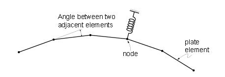
quadrilateral element type is recommended for modeling structures with
plate elements. When modeling a curved plate, the angles between two adjacent
elements should remain at less than 10˚. Moreover, the angles should not
exceed 2~3˚ in the regions where precise results are required.
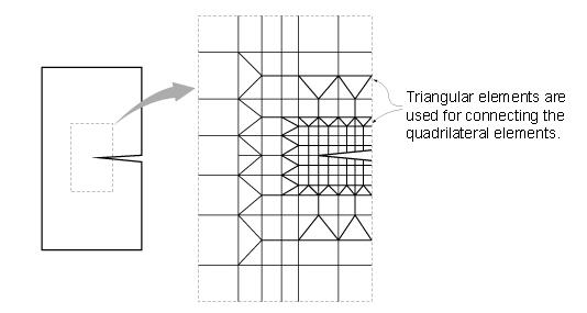
It is thus recommended that elements close
to squares be used in the regions where stress intensities are expected
to vary substantially and where detailed results are required.
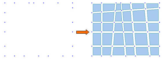
<Figure 3> Example of plate elements
used for a circular or cylindrical modeling
Plane Stress: Plane Stress Element
With
Drilling DOF: To consider the degree of freedom about the perpendicular
direction to the plat
Note This element can be used for modeling membrane structures that are subjected
to tension or compression forces in the plane direction only. Pressure
loads can be applied normal to the perimeter edges of the plane stress
element.
The plane stress element may
retain a quadrilateral or triangular shape. The element has in-plane tension,
compression and shear stiffness only.
Quadrilateral (4-node) elements,
by nature, generally lead to accurate results for the computation of both
displacements and stresses. On the contrary, triangular elements produce
poor results in stresses, although they produce relatively accurate displacements.
Accordingly, you are encouraged to avoid triangular elements at the regions
where detailed analysis results are required, and they are recommended
for the transition of elements only (<Figure 4>).
Singularity errors occur during
the analysis process, where a plane stress element is joined to elements
with no rotational degrees of freedom since the plane stress element does
not have rotational stiffness. In MIDAS/Gen, restraining the rotational
degrees of freedom at the corresponding nodes prevents the singularity
errors.
When a plane stress element
is connected to elements having rotational stiffness such as beam and
plate elements, the connectivity between elements needs to be preserved
using the rigid link (master node and slave node) option or the rigid
beam element option.
Appropriate aspect ratios for
elements may depend on the type of elements, the geometric configuration
of elements and the shape of the structure. However, aspect ratios close
to unity (1:1) and 4 corner angles close to 90?are recommended. If the
use of regular element sizes cannot be achieved throughout the structure,
the elements should be square shaped at least at the regions where stress
intensities are expected to vary substantially and where detailed results
are required.
Relatively small elements result
in better convergence.
<Figure
4> Crack modeling using quadrilateral/triangular elements
Note This element can be used to model a long structure, having a uniform cross
section along its entire length, such as dams and tunnels. The element
cannot be used in conjunction with any other types of elements.
Pressure loads can be applied normal to the
perimeter edges of the plane strain element.
Because this element is formulated on the
basis of its plane strain properties, it is applicable to linear static
analyses only. Given that no strain is assumed to exist in the thickness
direction, the stress component in the thickness direction can be obtained
through the Poisson's effect.
The plane strain element may retain a quadrilateral
or triangular shape. The element has in-plane tension, compression and
shear stiffness, and it has tension and compression stiffness in the thickness
direction.
Similar to the plane stress element, quadrilateral
elements are recommended over the triangular elements, and aspect ratios
close to unity are recommended for modeling plane strain elements.
Note This element can be used for modeling a structure with axis symmetry relative
to the geometry, material properties and loading conditions, such as pipes,
vessels, tanks and bins. The element cannot be used in conjunction with
any other types of elements.
Pressure loads can be applied normal to the
circumferential edges of the axisymmetric element.
Because this element is formulated on the
basis of its axisymmetric properties, it is applicable to linear static
analyses only. It is assumed that circumferential displacements, shear
strains and shear stresses do not exist.
Similar to the plane stress element, quadrilateral
elements are recommended over the triangular elements, and aspect ratios
close to unity are recommended for modeling axisymmetric elements.
Note This element is used for modeling three-dimensional structures, and its
types include tetrahedron, wedge and hexahedron.
Pressure loads can be applied normal to the
surfaces of the elements or in the X, Y, and Z-axes of the GCS.
The use of hexahedral (8-node) elements produces
accurate results in both displacements and stresses. On the other hand,
using the wedge (6-node) and tetrahedron (4-node) elements may produce
relatively reliable results for displacements, but poor results are derived
from stress calculations. It is thus recommended that the use of the 6-node
and 4-node elements be avoided if precise analysis results are required.
The wedge and tetrahedron elements, however, are useful to join hexahedral
elements where element sizes change.
Solid elements do not have stiffness to rotational
d.o.f. at adjoining nodes. Joining elements with no rotational stiffness
will result in singular errors at their nodes. In such a case, MIDAS/Gen
automatically restrains the rotational d.o.f. to prevent singular errors
at the corresponding nodes.
When solid elements are connected to other
elements retaining rotational stiffness, such as beam and plate elements,
introducing rigid links (master node and slave node feature in MIDAS/Gen)
or rigid beam elements can preserve the compatibility between two elements.
An appropriate aspect ratio of an element
may depend on several factors such as the element type, geometric configuration,
structural shape, etc. In general, it is recommended that the aspect ratio
be maintained close to 1.0. In the case of a hexahedral element, the corner
angles should remain at close to 90° It is particularly important to satisfy
the configuration conditions where accurate analysis results are required
or significant stress changes are anticipated. It is also noted that smaller
elements converge much faster.
Wall:
Wall Element
In case of Wall,
the wall combination number is additionally entered. Check() Auto Inc. to increase the ID by 1, as wall elements are
entered.
Material
Select a material property number, or select
a material property name provided that the material property data have
been already defined.
No.:
Type in a number on the keyboard or use the mouse to enter the number.
Name:
Select a material property name.
Click to add, inquire, modify
or delete material property data. Material properties can be entered either
before or after creating elements.
Section (or Thickness)
Select a section (thickness) number, or select
a section(thickness) name provided that the section (thickness) data have
been already defined.
No.:
Type in a number on the keyboard or use the mouse to enter the number.
Name:
Select a section (thickness) name.
Click to add, inquire, modify
or delete section (thickness) data. Section data can be entered either
before or after creating elements.
Orientation
When elements are of a line type (Truss,
Beam, etc.), Beta Angle or the coordinates of Reference Point are specified
to define the orientation of sections.
If the coordinates of the Reference Point
are entered, MIDAS/Gen internally computes the angle of the point and
enters the angle as a Beta Angle automatically.
If the coordinates of the Reference Vector
are entered, z-axis of an element is placed on the plane containing the
Vector.
MIDAS/Gen uses the Beta Angle (β) conventions
to identify the orientation of each cross-section. The Beta Angle relates
the ECS to the GCS. The ECS x-axis starts from node N1 and passes through
node N2 for all line elements. The ECS z-axis is defined to be parallel
with the direction of "l"
dimension of cross-sections. That is, the y-axis is in the strong axis
direction. The use of the right-hand rule prevails in the process.
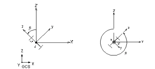
If the ECS x-axis for a line element is parallel
with the GCS Z-axis, the Beta angle is defined as the angle formed from
the GCS X-axis to the ECS z-axis. The ECS x-axis becomes the axis of rotation
for determining the angle using the right-hand rule. If the ECS x-axis
is not parallel with the GCS Z-axis, the Beta angle is defined as the
right angle to the ECS x-z plane from the GCS Z-axis (See below).
(a) Case of vertical members (ECS x-axis is parallel with
the global Z-axis)
(b) Case of horizontal or diagonal members (ECS x-axis
is not parallel with the global Z-axis.)
Beta
Angle Conventions
Nodal Connectivity
Enter the node numbers defining the element
in accordance with the (N1, N2,...) sequence shown in the figure that
appears upon selecting Element Type.
Use the following two methods to enter the
element's nodal connectivity.
Type in the node
numbers in the Nodal Connectivity field.
Click the Nodal
Connectivity field, which will turn the background color to pale green.
Then, assign consecutively the desired node points in the Model Window
to enter elements. If there is no node at the assigned point, a new node
is created. It is quite convenient to create elements when Point
Grid (or Line Grid) , Grid Snap,
Node Snap and Elements Snap. are activated.
If Ortho option is selected the mouse cursor
snaps to the entities only in the directions parallel to the currently
active coordinate axes (UCS or GCS) from the first point selected.
The nodal
locations defining the new elements are entered by directional axes, relative
distances or element lengths/angles.
x,y,z:
The coordinates of the connecting point of an element are entered in the
data entry field, then press the enter key on the keyboard or click .
dx, dy,
dz: Enter a distance relative to the reference point and press
the enter key on the keyboard or click , If characters are
included in the string of numerical values, MIDAS/Gen recognizes them
as a relative distance, irrespective of which one of the three methods
of data entry is selected
Example:
'0,20,10' of ' dx, dy, dz' are expressed as '@10, 20, 10' .
l, theta:
l represents the length of an element. Theta represents the angle by which
the element direction is rotated with respect to x-axis of the current
coordinate system. Once the data are entered, press the enter key on the
keyboard or click .
If characters, '@' and/or '<' are included
in the string of numerical values, MIDAS/Gen recognizes the numbers as
l and theta, irrespective of which one of the three methods of data entry
is selected.
Example:
'10, 15' of 'l, theta' are expressed as '@10<15'
Note
The origin of the current coordinate system is assigned as the reference
point initially. Subsequently, the last point used becomes the reference
point. To confirm the location of the reference point, enter '@0' in the
data field and press the Enter key on the keyboard.
Intersect
If Intersect
Node is selected and existing nodes are on the element, the element
is divided at the existing nodal positions irrespective of the element
type.
If Intersect
Element is selected and the line element created intersects with
an existing line elements, nodes are automatically created and the line
elements are divided at the intersections.
If Create
Intersecting Nodes is selected and even if there are no interior
nodes in the created plate and solid elements, nodes are created at the
intersections of the lines extended by the exterior nodes and plate or
solid elements are subsequently created.
 Create Elements
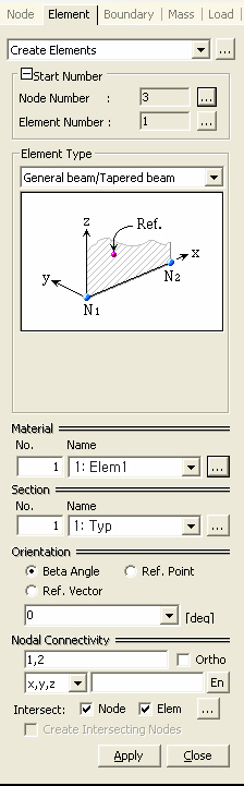
 to the right of
  Start Node Number
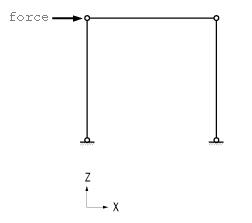
.jpg) ) Auto Inc. to increase the ID by 1, as wall elements are
entered.
) Auto Inc. to increase the ID by 1, as wall elements are
entered.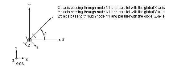
 Nodal Connectivity
 .
.