Story
  | 
| 
 
  | 
| 
 
  | 
| 
 Story is used to define the floor levels if the analysis model is a building. Because the positions of the stories are defined using the GCS Z-axis coordinates, the floor planes of the building must inevitably be parallel to GCS X-Y plane. 
 Story is used for the following purposes: 
 
 
 Data entry and results data related to Story In general, stories are identified by floors in a building. In generating an analytical model for a building structure, floors are considered as rigid diaphragms, and lateral loads such as wind and seismic loads are assumed to act on the floor diaphragms. 
 Also in design of the building structure, results related to Story are required, which are story stiffness ratios, story eccentricity ratios, story drifts, story shear forces, etc. 
 1. Auto generation of story data 
 Midas Gen provides the auto-generation function for story data by automatically recognizing the z-coordinates of nodes in the structure. (In the main menu, Model > Building > Story) 


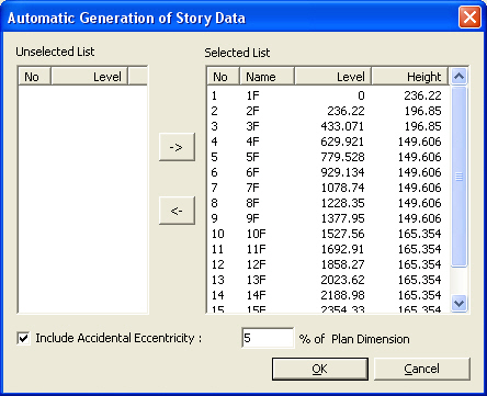
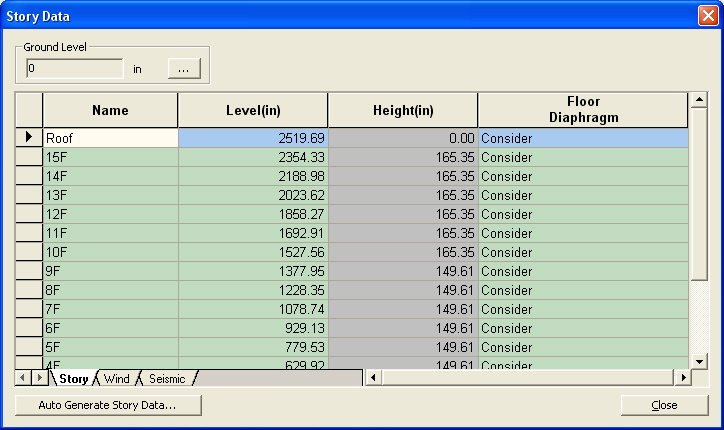
 Auto-generated story data 
 If the user defines the Ground Level, basements can be considered to which auto-generated wind and seismic loads are not applied. Floor diaphragms are automatically considered for all floors except for the lowest level. In order to release the floor diaphragms for specific stories, select Model>Boundary>Disconnect Diaphragm in the main menu. 
 
 
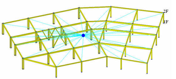
 Display of story diaphragm 
 2. Check the results related to story 
 Midas Gen provides the following results: 
 
 
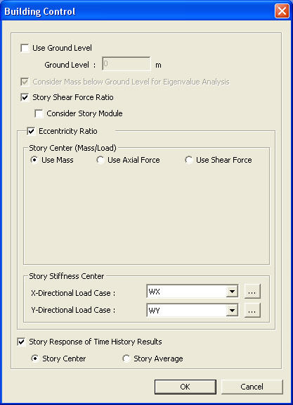
 Story shear force distribution ratio can be produced when Story Shear Force Ratio (Model>Building>Control Data) is checked on before analysis is performed. 


 Calculation methods for Story Center  | 
| 
 
  | 
| 
 
  | 
| 
 
  | 
| 
 From the Main Menu select Model > Building > Story. 
 Select Geometry > Building > Story in the Menu tab of the Tree Menu. 
 Shortcut key: [F10]  | 
| 
 
  | 
| 
 
  | 
| 
 
 
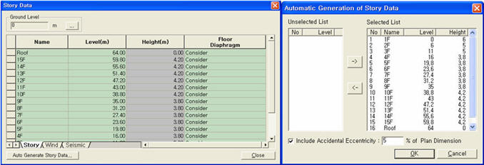
 Use the Table Entry function to directly 
 enter the story data in the Table or click  
 
 
 Story Data dialog box
 Ground Level
 The ground level is expressed by the coordinate of the GCS Z-axis. The stories from the Base to the ground level are assumed as underground stories and designated as 'B1', 'B2'... during the auto-generation of story data. 
 
 Direct Entry Method of Story Data in Table
 Refer to "Usage of Table Tool" 
 in the Story Entry Table to enter the following data: Terminology 
 Familiarize with Usage 
 Basic directions (Cell motion, selection, size control, etc.) 
 Data manipulation (Add, delete, modify data, etc.) 
 Copy/Paste data using clipboard 
 Supplementary Table functions 
 Table Sorting 
 Table format setting 
 Auto-fit column width 
 Graph printing 
 Supplementary functions by Table types 
 Node/Element Table 
 Results Table 
 The command supplies 3 Table dialog boxes related to stories and the data entries for each dialog box are as follows : 
 
 Story tab
 Name : Story name 
 Level : Story height (elevation) 
 Height : Floor to floor height 
 Floor Diaphragm : Assign Floor Rigid Diaphragm to the relevant story. This function constrains Dx, Dy and Rz to the relevant story. 
 Note 1 If Do not consider is selected for Floor Diaphragm and Membrane Type of wall is defined, Singular Warning message is displayed when the analysis is carried out. This is because Membrane Type of wall does not have out-of-plane stiffness. It can be resolved by changing the Membrane Type into Plate Type. 
 Note 2 If Floor Diaphragm is considered, all masses of the relevant story are lumped into Mass Center. The mass data lumped into Mass Center can be checked from Query> Story Mass Table. 
 Note 3 When a Support condition (3 translational degrees of freedom and 3 rotational degrees of freedom restrained) is assigned to a certain node on Floor Diaphragm, the degrees of freedom overlapping with Floor Diaphragm are automatically released. 
 Note 4 In case of stepped slabs, consider Floor Diaphragm to each slab and define Elastic Link-Rigid Type to the slab gap. 
 
 Wind tab
 Name : Story name 
 Floor Width X-Dir. : Effective width of the building in X-axis, subjected to GCS Y-direction wind load 
 Floor Width Y-Dir. : Effective width of the building in Y-axis, subjected to GCS X-direction wind load 
 Floor Center Xc : Coordinate of the position in GCS X-direction, to which the wind load is applied 
 Floor Center Yc : Coordinate of the position in GCS Y-direction, to which the wind load is applied 
 
 Seismic tab
 Name : Story name 
 Eccentricity X - Dir. Accidental eccentricity distance in X-direction to calculate the accidental eccentricity moments due to the seismic loads at each story in GCS Y-direction when the equivalent static seismic load is calculated 
 Eccentricity Y - Dir. Accidental eccentricity distance in Y-direction to calculate the accidental eccentricity moments due to the seismic loads at each story in GCS X-direction when the equivalent static seismic load is calculated 
 
 Method to auto-generate story data
 Click  
 Note MIDAS/Gen assumes the Z-coordinates of all 
 the entered nodes as story levels and includes them in the Selected List. 
 Click  


 Story Data dialog box


 When a static seismic load needs to be automatically calculated, check on the box to consider Accidental Eccentricity for torsional moment. The magnitude of the eccentricity is specified in percentage relative to a Plan Dimension. 
  | 
| 
 
  |