Enter floor loads within a "closed" planar polygon. The floor
loads are converted into line beam loads or in-span, concentrated beam
loads applied to the top of wall or beam elements.
When the floor load and shape are typical for each story, as in buildings,
it is very convenient to use the simultaneous load using Copy Floor Load
function.
The procedure for converting the distributed pressure loads, such as
dead, live, roof or snow loads acting on a particular plane, into effective
loads (concentrated loads or distributed loads) acting on the structural
members (beam or wall) is extremely complex. This command automatically
converts these pressure loads into effective loads acting on beams or
walls.
The area loaded by a floor load is defined by a "closed" polygon
made up by the corner nodes along the boundary. This area must lie on
a plane but does not necessarily have to be parallel with any GCS axis.
When the area loaded by a floor load is not a closed polygon, create
a dummy beam to form a closed polygon and then apply the floor load.
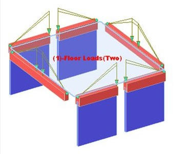
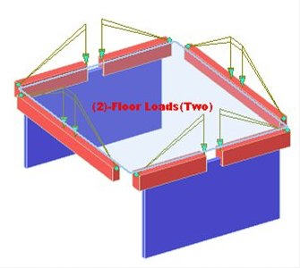
Note
In the older version, when a single wall had divided beams on top, floor
loads could not be entered. But in the new version, floor loads can be
entered even in the aforementioned case. Example is illustrated below.
In
the old version
In
the new version
From the Main
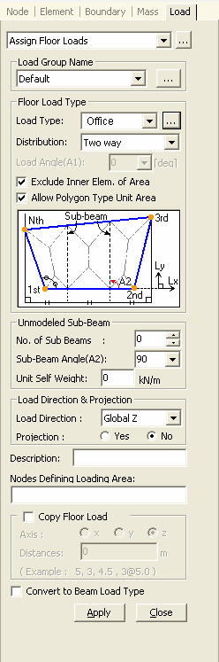
Menu select Load > Assign Floor Loads.
Select Static Loads
> Assign Floor Loads in the Menu tab of the Tree Menu.
Load
Group Name
Select the desire Load
Group that will include the entered Assign Floor Loads data. Select "Default",
if a Group assignment is unnecessary. Click to the right
to add, modify or delete Load Groups.
Floor Load cannot be
removed if it is once loaded in a construction stage. Any
temporary load needs to be defined in a different Load Group in construction
stage analysis.
Floor
Load Type
Load
Type : Select the Floor Load Type defined by Define
Floor Load Type. Click to the right to define, add,
modify or delete new or existing floor load types if necessary.
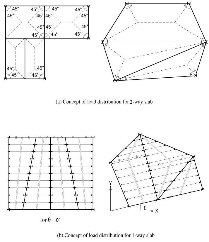
Distribution Type
:One Way Distribution
: Two Way Distribution
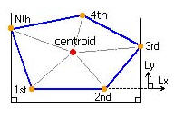
: Polygon-Centroid
Load distribution based
on the areas of triangular segments created by dividing a polygon relative
to the centroid
: Polygon-Length
Load Distribution proportional
to the lengths of the sides of a polygon
Exclude
Inner Elem. of Area: This is used not to load the elements within
the area of an assigned floor load. This
becomes useful for example when we wish not to consider floor bracings
as a part of floor framing.
Allow Polygon
Type Unit Area: This is used to apply floor load in the area of
a concave polygon with an internal angle exceeding 1800
. If Two Way is selected in Distribution, 'Allow Polygon Type Unit Area'
can be checked.
Note
Tributary areas are marked
when Load >Floor Load Area is checked in Display.
Note
Colors can be assigned to
tributary areas by using Color >Load >Floor Load Area in Display
Option.
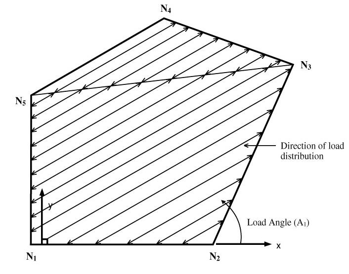
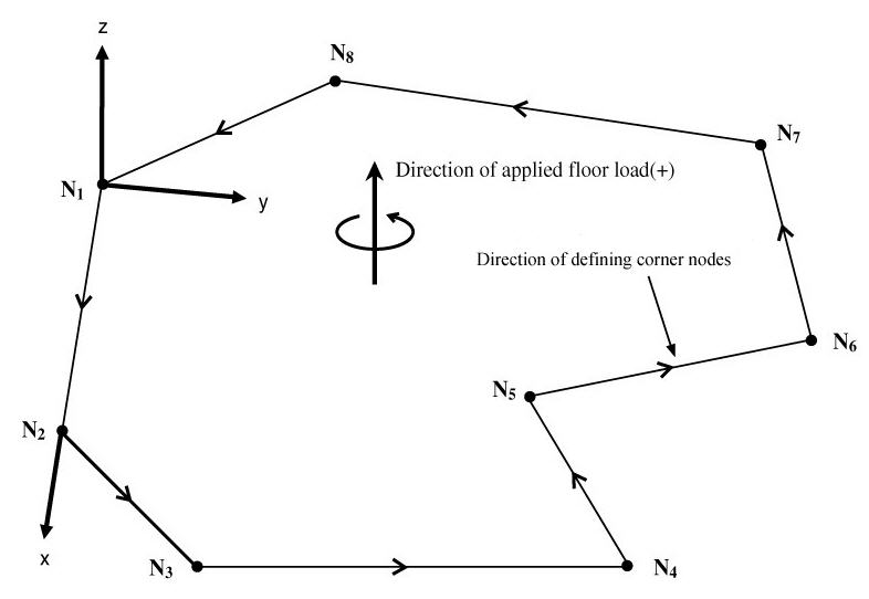
Load Angle(A1):
Angle defining the direction of the load to be distributed.
Load Angle is applicable only for One Way
Distribution. It is an angle formed by the line connecting the 1st node
to the 2nd node defining the loaded area and the load distribution direction.
The sign convention for the angle follows the right-hand rule. The positive
angle (+) is determined by the angular direction of the assignment sequence
of the corner nodes defining the loaded area. (Refer to Figs. 2,3)
Unmodeled Sub-Beam
A typical floor system may entail one-way
slabs supported on beams supported on girders.
Beam members (referred to as sub-beams) supported
on girders in a typical structural system do not influence the structural
behavior. They simply act as media to transfer the floor loads. As a result,
beam members are typically excluded in the analysis model.
Following the gravity system concept, MIDAS/Gen
enables the user to specify fictitious beams to properly account for floor
gravity loads. The fictitious (unmodeled) beams respect the load distribution
paths.
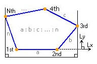
The loaded area is defined by the corner
nodes entered in 'Nodes Defining Loading Area'.
The shape of a sub-loaded area formed by
beams, girders and walls within the loaded area must be a triangle or
a quadrangle.
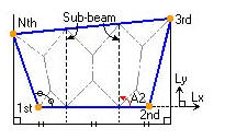
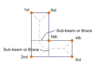
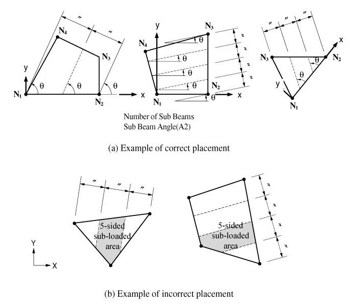
No. of
Sub-Beams : Number of sub-beam members placed in a sub-area (Refer
to Note
and Figs. 4 & 5)
Sub-Beam
Angle(A2) : Placement angle of the sub-beam members (Refer to Figs. 4, 5)
Unit Self
Weight : Self-weight per unit length of a sub-beam member (load/length)
Note
Self-weight of Sub-Beam
is always applied in the Global Z direction, regardless of the Load Direction.
In case the direction of self-weight of Sub-Beam (Global Z) is consistent
with the Load Direction, self-weight of Sub-Beam is integrated into the
floor load. Otherwise, individual loads are generated.
Load Direction & Projection
Select the load direction and projection
option of the floor loads.
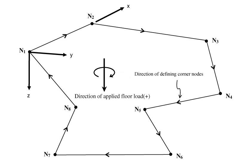
The coordinate system for the loaded area
is determined while the loaded area is assigned. The direction from the
1st corner node to the 2nd corner node corresponds to the local x-direction
of the plane. Using the rotational direction following the assignment
sequence of the corner nodes and the right-hand rule, the axis of the
rotation becomes the local z-direction. The direction perpendicular to
the x & z-directions at the first node is the local y-direction. (Refer
to Fig.3)
Local x:
Floor load applied in the x-direction of the floor plate local coordinate
system (Refer to Fig.3)
Local y:
Floor load applied in the y-direction of the floor plate local coordinate
system (Refer to Fig.3)
Local z:
Floor load applied in the z-direction of the floor plate local coordinate
system (Refer to Fig.3)
Global
X: Floor load applied in GCS X-direction
Global
Y: Floor load applied in GCS Y-direction
Global
Z: Floor load applied in GCS Z-direction
<Figure
1> Conversion of floor load into distributed loads applied to the beam
elements (in the absence of sub-beams)
<Figure
2> Notion of 'Load Angle(A1)' in the case of One Way Distribution
<Figure
3> Relationship between the floor plate local coordinate system and
the assignment direction of corner nodes
<Figure
4> Definitions of 'No. of Sub-Beams' and 'Sub-Beam Angle(A2)'
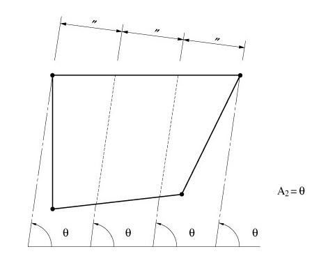
<Figure 5> Notion of Sub-Beam Angle(A2) (in the
case where 'No. of Sub-Beams'=2)
Projection
When the Floor Load direction corresponds to 'Global X, Y or Z', select
the option wether or not to project the floor load.
Yes:
when the floor load is applied to the area projected on a plane perpendicular
to the loading direction
No:
when the floor load is applied along the plane of the structure
For instances, select 'Yes' for snow load
and select 'No' for dead load applied to a sloped roof.
Description
Enter a short description.
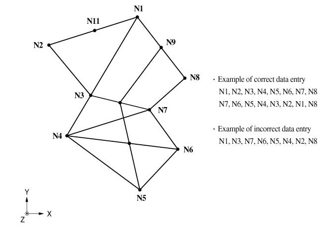
Nodes Defining Loading Area
Assign the corner nodes defining the loaded area consistently in the chosen
rotational direction. You may directly enter the node numbers or click
the entry field and the nodes in the Model Window using Node Snap. The
floor plate local coordinate system and the loading signs are defined
by the assignment sequence of the corner nodes. (Refer to Fig.
3)
The corner nodes can be consecutively entered
as shown in <Fig. 6>. Non-corner
nodes such as N9 and N11 need not be defined.
The nodes are selected at the corners of
non-straight boundary edges.
All the beam
elements (or wall elements) within the boundaries of the loaded area
must retain sub-loaded areas in the form of triangles and quadrangles.
If the beam (or wall) elements are overlapped on a same line or the intersections
are not joined by nodes errors will be committed.
When using the mouse cursor in the Model
Window, consecutively assign the corner nodes and reassign the first node
to complete the polygon.
<Figure 6> Data entry of corner nodes to define
the loaded area subjected to floor loads
Copy Floor Load
Copy the entered floor load onto other floor
plates of identical shapes (dimensions).
Axis:
Assign copy direction
x:
UCS x-direction
y:
UCS y-direction
z:
UCS z-direction
Distances:
Multiple copy distances
Specify relative distances as many times
as necessary to copy the floor load.
Note
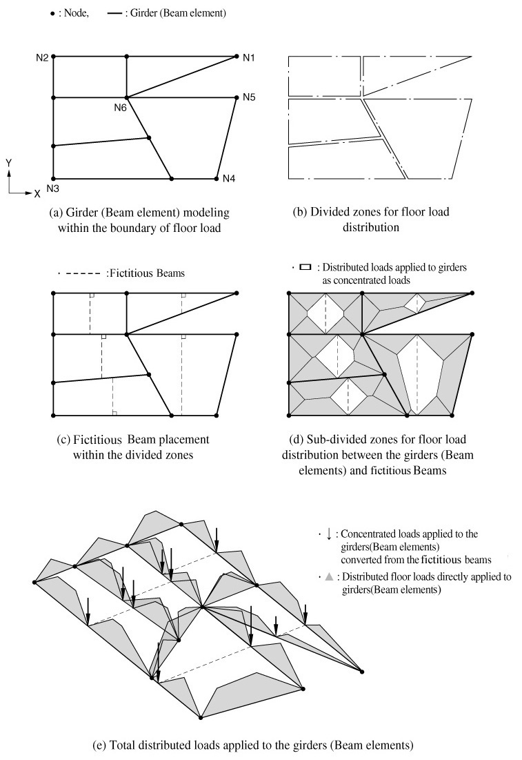
Using the notion of sub-beams, the method of converting the floor load
into the loads applied to the beam or wall elements in the form of distributed
loads or in-span concentrated loads is as follows:
The
area to be loaded by the floor load is defined by the corner nodes as
shown in <Fig. 7(a)>. The sub-loaded areas consisted of polygonal
units formed by triangles or quadrangles are created by the beam (or wall)
elements placed within the boundaries as shown in <Fig.
7(b)>.
Once
the 'No. of Sub-Beams' is defined, the sub-loaded areas are further divided
as shown in <Fig. 7(c)>. (No. of Sub-Beams = 1 in <Fig.
7(c)>)
According
to the distribution concept shown in <Fig.
7> on the basis of re-divided
sub-loaded areas, the distributed loads are applied to the beam (or wall)
elements and the sub-beams as shown in <Fig.
7(d)>. The distributed loads
applied to the sub-beams are converted into (assume that both ends are
pinned) the reactions at both ends.
The
reactions transmitted from the sub-beams and the distributed loads acting
on the beam (or wall) elements are finally applied to the beam (or wall)
elements as shown in <Fig.
7(e)>.
The
sub-beams are placed so as to form an angle 'A2' with the floor plate
local x-axis as shown in <Fig.
4(a)>. The sub-beams are placed
at an equal spacing of 'No. of Sub-Beams' +1. The spacings are created
by dividing a fictitious line perpendicular to the sub-beams.
The length of the fictitious line is determined
by two projecting lines passing though the furthermost corner nodes, parallel
with the sub-beams.
The polygonal shapes of sub-loaded areas formed
by the sub-beams and existing beam (or wall) elements can be only triangles
or quadrangles.
<Fig.
4(b)> presents the pentagons
(shaded area) which deviate from the basic shape requirements. An error
will result.
<Figure 7> Conversion of the floor plate load into
distributed loads acting on beam elements (or on the top of wall elements)
Convert to Beam Load Type
If beam or wall elements are subsequently
added to an existing loaded plane, the floor load is automatically redistributed
reflecting the added elements. Use this function to convert the floor
load into beam loads when the floor load is not to be applied to the added
elements.
Note
When the magnitude of the floor load is to be changed, modify only the
value of Floor Load Type. Then, the modified load is applied to the model.
However, if Convert to Beam Load Type has been selected and Floor Load
is revised, the modification is meaningless. The loads to be applied on
the beam elements must be changed directly.
Note
Warning for applying Floor Load
The Floor Load is
applied to triangular or quadrangular areas demarcated by beam or wall
elements. When sub-beams are used, the shape requirements must remain
intact.
 Load
Group Name
Load
Group Name to the right
to add, modify or delete Load Groups.
to the right
to add, modify or delete Load Groups.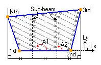
 Nodes Defining Loading Area