Overturning Moment Table
|
|
|
|
|
|
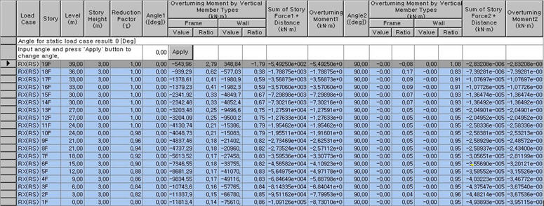
Overturning moments due to static and dynamic loadings are calculated, and the results are tabulated in a spread sheet format.
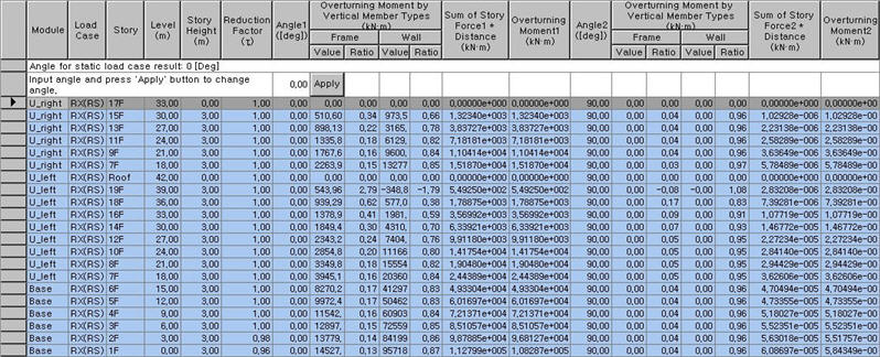
When “Consider Story Module"under "Story Shear Force Ratio" is checked in the “Model/Building/Control Data", accurate shear forces can be obtained for the story overlapping the upper Module and the lower Module.
When Modules are defined in Results > Result Tables > Story > Define Module, the Module data is displayed in the first column of the table.
"Story Shear Force Ratio" in "Model/Building/Control Data" must be checked for this function, which is checked as the Default.
Table Tool in MIDAS/Gen offers a variety of powerful built-in functions. Refer to the following items for detail directions:
Usage of Table Tool
Terminology
Familiarize with Usage
Basic directions (Cell motion, selection, size control, etc.)
Data manipulation (Add, delete, modify data, etc.)
Copy/Paste data using clipboard
Supplementary Table functions
Table Sorting
Table format setting
Auto-fit column width
Graph printing
Supplementary functions by Table types
Node/Element Table
Results Table |
|
|
|
|
|
|
|
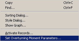
From the Main Menu select Results > Result Tables > Story > Overturning Moment Table
Select Result Tables > Story > Overturning Moment Table in the Tables tab of the Tree Menu. |
|
|
|
|
|
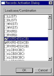
From Record Activation Dialog, select the load cases/combinations for which Overturning Moment will be calculated.
Record Activation dialog box
Refer to Usage of Table Tool and check the following data:
Load Case: Load case/Combination
Story: Story number
Level: Elevation of the Story
Story Height: Story (floor to floor) Height
Angle: Specify a load direction
Note1
1. Reduction Factor(τ)
Reduction Factors for Overturning Moments are applied as follows:
(1) 10 stories from the top: 1.0 (2) 20th story from the top and below: 0.8 (3) Between 10th and 20th stories from the top: interpolated between 1.0 and 0.8
2. Overturning Moment by Vertical Member Types
Value and ratio of the overturning moment in the direction specified by the Angle, which is contributed by the Frame and Wall.
3. Sum of Story Force * Distance
The values from the equation below are multiplied by the 'Scale-up Factor' invoked from 'Set Overturning Moment Parameters'. The Reduction Factors have not been applied to Overturning Moments here.
4. Overturning Moment
The Reduction Factors have been applied to Overturning Moments here.
The Reduction Factors for Overturning Moments (τ) are obtained by an approximate method, which are intended to consider the effects of higher modes of a highrise building for the results of static analysis. IBC2000 states that Define Reduction Factor of Set Overturning Moment Parameters can be set to τ=1.0 for dynamic analysis.
5. Set Overturning Moment Parameters
Right-click on the table and select "Set Overturning Moment Parameters" to enter Scale Factor and Reduction Factor values.
Scale Factor Scale up Factors calculated for dynamic analysis
Reduction Factor Fixed (1.0): Reduction Factor, 1.0, is applied to al the stories. Auto Calculation: Reduction Factor for each story is automatically calculated as per "1.Reduction Factor".
The Module colun is generated only when the Modules are defined. Overturning moments are calculated as per the following Note.
Note 1. τ : Apply different τ values to upper Modules and apply the greater of those τ values to Base Module. 2. Overturning moment for the top floor of Base Module is not generated.
Module: Module name is defined in Define Module
Load Case: Load case/Combination
Story: Story number
Level: Elevation of the Story
Story Height: Story (floor to floor) Height
Angle: Specify a load direction
Note1 For static loads, once the load direction is input as Angle, overturning moment is obtained for the loads applied in the specified direction. For response spectrum loads, a certain overturning moment is generated irrespective of the specified load direction, since in this case the overturning moment is calculated with respect to the direction that is specified when response spectrum loads are entered.
1. Reduction Factor(τ)
Reduction Factors for Overturning Moments are applied as follows:
(1) 10 stories from the top: 1.0 (2) 20th story from the top and below: 0.8 (3) Between 10th and 20th stories from the top: interpolated between 1.0 and 0.8
2. Overturning Moment by Vertical Member Types
Value and ratio of the overturning moment in the direction specified by the Angle, which is contributed by the Frame and Wall.
3. Sum of Story Force * Distance
The values from the equation below are multiplied by the 'Scale-up Factor' invoked from 'Set Overturning Moment Parameters'. The Reduction Factors have not been applied to Overturning Moments here.
4. Overturning Moment
The Reduction Factors have been applied to Overturning Moments here.
The Reduction Factors for Overturning Moments (τ) are obtained by an approximate method, which are intended to consider the effects of higher modes of a highrise building for the results of static analysis. IBC2000 states that Define Reduction Factor of Set Overturning Moment Parameters can be set to τ=1.0 for dynamic analysis.
5. Set Overturning Moment Parameters
Right-click on the table and select "Set Overturning Moment Parameters" to enter Scale Factor and Reduction Factor values.
Scale Factor Scale up Factors calculated for dynamic analysis
Reduction Factor Fixed(1.0): Reduction Factor, 1.0, is applied to al the stories. Auto Calculation: Reduction Factor for each story is automatically calculated as per "1.Reduction Factor".
Context Menu (Set Overturning Moment Parameters)
Set Overturning Moment Parameters dialog box |
|
|
 When Modules are not defined