Select the structural frame type (braced/unbraced) with respect to the
global X- and Y-directions. Select the auto-calculation option for the
effective buckling length factors for column members.
From the Main
Menu select Design
> General Design Parameter > Definition of Frame.
From the Menu
tab of
the
Tree Menu select Design
> General Design Parameter > Definition of Frame.
The following dialog box is used to enter
the data:
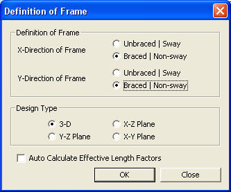
Definition of Frame dialog box
Definition of Frame
Define the type of structural frame.
X-Direction
of Frame
Select Unbraced | Sway or Braced | Non-sway frame in the global X-direction
(Default = Unbraced | Sway).
Y-Direction
Frame
Select Unbraced | Sway or Braced | Non-sway frame in the global Y-direction
(Default = Unbraced | Sway).
Design Type
When members in a 3-D structure are designed,
a Design Type is selected to account for only the forces in the selected
plane to design the members as a 2-D frame.
3 - D:
Design is carried out while accounting for all the member forces in the
3-D frame.
X - Z Plane:
Design is carried out while accounting for only the member forces in the
GCS X-Z plane as a 2-D frame.
Y - Z Plane:
Design is carried out while accounting for only the member forces in the
GCS Y-Z plane as a 2-D frame.
X - Y Plane:
Design is carried out while accounting for only the member forces in the
GCS X-Y plane as a 2-D frame.
Note
This option may become handy when a structure with continuity in one direction
is to be designed as a 2-D frame.
Auto Calculate Effective Length Factors
Select if the effective buckling length factors
are to be automatically calculated.
(1) Calculate
the stiffness, S (=EI/L), of the members which are connected to the ‘Member
a’ as shown in the figure 1 below. If the joint of the flexural member
is fixed or hinged as shown in the figure 2 below, the stiffness, S, is
modified as below.
Fixed joint: S = (1/1.5)* EI/L
Hinge: S= (1/2.0)* EI/L
Where,
E:
Modulus of elasticity
I:
Moment of inertia of section
L:
Span length of flexural member measured from center to center of joints
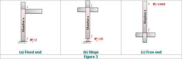
(2) Calculate
Ψ and Ψ. Ψ is
the ratio of Σ(EI/lc) of compression members and Σ(EI/l) of flexural members
in a plane at one end of a compression member. As shown in the figure
3 below, if the end of the compression member is fixed or hinged, Ψ is
taken as 1 or 10 respectively. If the compression member is not connected
to any flexural member, Ψ is taken as 1000.
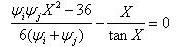
(3) Calculate the solution,
X, in the stability equation below.
Braced
/ Nonsway frames
Unbraced / Sway frames
Where, Ψ: Ratio of Σ(EI/lc) of compression
members to Σ(EI/l) of flexural members in a plane at one end of a
compression member.
(4) Calculate
the effective length factor, K
[Reference: "Steel structures"
(1982), Ballio and Mazzolani]
: Enter the selection
and close the dialog box.
: Do not enter the selection
and close the dialog box.
 Definition of Frame
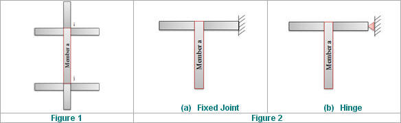


 : Enter the selection
and close the dialog box.
: Enter the selection
and close the dialog box. : Do not enter the selection
and close the dialog box.
: Do not enter the selection
and close the dialog box.