Brace Design
| ||||||||||||||||||||||||||||||||||||||||||||||||
|
| ||||||||||||||||||||||||||||||||||||||||||||||||
|
| ||||||||||||||||||||||||||||||||||||||||||||||||
|
Using the results obtained from the analysis of the entire structure and additional design data, automatically design concrete brace members according to the following design codes: American Concrete Institute (ACI318-89, ACI318-95, ACI318-99, ACI318-02 & ACI318-05), Canadian Standards Association(CSA-A23.3-94), British Standard (BS8110-97) and European Standard (ENV 1992-1-1:1992 & EN 1992-1-1:2004).
Architectural Institute of Japan (AIJ-WSD99), Architectural Institute of Korea (AIK-USD99), Korean Society of Civil Engineers (KSCE-USD96), Korean Concrete Institute (KCI-USD03 & KCI-USD99), Architectural Institute of Korea (AIK-WSD2K), China Standard((GB50010-02) ,Taiwan Standard (TWN-USD92) and Indian Standard (IS456:2000) are available upon request. It performs automatic design for nonlinear brace members.
Note | ||||||||||||||||||||||||||||||||||||||||||||||||
|
| ||||||||||||||||||||||||||||||||||||||||||||||||
|
| ||||||||||||||||||||||||||||||||||||||||||||||||
|
| ||||||||||||||||||||||||||||||||||||||||||||||||
|
From the Main Menu select Design > Concrete Code Design > Brace Design.
Shortcut key : [Ctrl]+3 | ||||||||||||||||||||||||||||||||||||||||||||||||
|
| ||||||||||||||||||||||||||||||||||||||||||||||||
|
| ||||||||||||||||||||||||||||||||||||||||||||||||
|
The automatic design results are based on the maximum axial forces and biaxial moments evaluated on the basis of P-M interaction diagrams and shear forces in accordance with the load combinations for concrete design.
When the elements to be designed are not assigned as Members, the design is executed for the I- and J-ends of each element. When the elements are assigned as Members, design is executed at positions I, 1/2 & J of each member.
The automatic design results can be sorted by members or section properties.
The automatic design results sorted by elements are based on the maximum axial forces, biaxial moments and shear forces calculated at the positions (I, 1/2, & J) of each element in accordance with the load combinations for concrete design. Factored strength ratios with respect to the design strengths are evaluated on the basis of P-M interaction diagrams.
The automatic design results sorted by section properties are based on the results that produce the maximum strength ratios in the P-M diagrams by considering all the elements and locations pertaining to each section property in accordance with the load combinations for concrete design.
The results appear in blue when the automatic design for the given properties is satisfactory, otherwise they appear in red which represent the results are unsatisfactory.
The automatic design provides optimal rebar sizes, the number of rebars and the number of rows of rebars satisfying the rebar spacing and ratio, using the main rebars (maximum 5 types) and sub-rebars (1 type) entered by the user.
When the user elects not to enter the rebar data, the program automatically designs the members using #7 for the main rebars and #3 for the sub-rebars.
The automatic design results are produced in the unit system selected by the user.
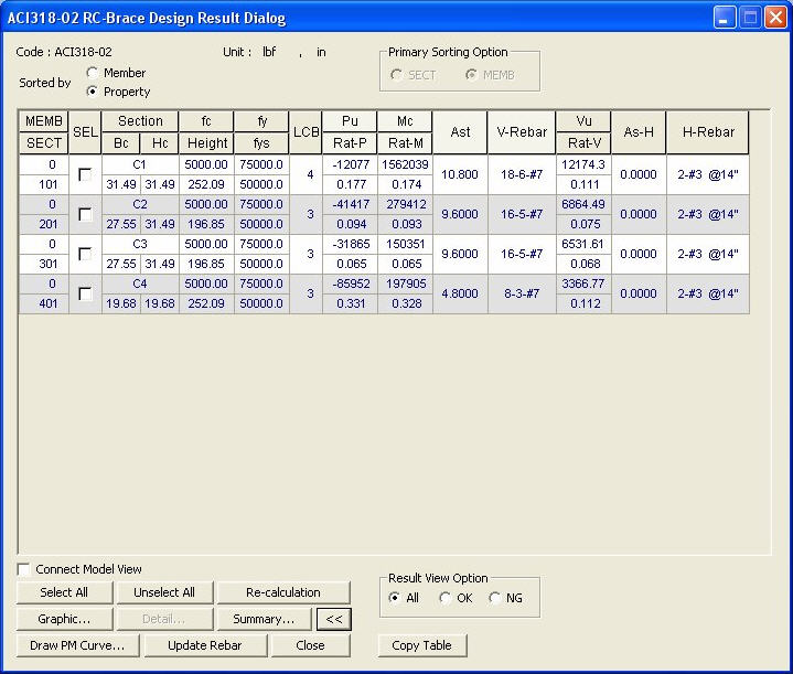
ACI318-02 RC-Brace Design Results Dialog Box
MEMB: Member number
SECT: Section property number
SEL: Select members for strength verifications and production of results
Note
Section : Section name
Bc, Hc: Width, height (depth) of brace member
Height: Height (length) of brace member
f'c: Design compressive strength of concrete
fy: Design yield strength of main rebars
fys: Design yield strength of shear rebars
CHK:
Status of automatic design results (Results are produced in the
= "OK": Automatic design results satisfy the design strength for the factored axial force, moment and shear force
= "P**": Automatic design results do not satisfy the design strength for the factored axial force
= "*M*": Automatic design results do not satisfy the design strength for the factored moment
= "**V": Automatic design results do not satisfy the design strength for the factored shear force
= "PM*": Automatic design results do not satisfy the design strength for the factored axial force and moment
= "*MV": Automatic design results do not satisfy the design strength for the factored moment and shear force
= "P*V": Automatic design results do not satisfy the design strength for the factored axial force and shear force
= "PMV": Automatic design results do not satisfy the design strength for the factored axial force, moment and shear force
LCB: Load combination yielding the maximum factored load ratio determined from the P-M diagram. The program examines all the load combinations and sectional locations of the relevant member or section property to find the maximum ratio.
Pu: Factored compression (tension) force acting on the brace member under the load combination displayed in LCB
= Pu > 0: Compressive axial force acting in the member's axial direction
= Pu < 0: Tensile axial force acting in the member's axial direction
Rat-P:
Ratio of the factored axial force (Pu)
to the design axial strength (
Mu: Factored bending moment in the brace member under the load combination displayed in LCB. The value is calculated as follows :
Rat-M
: Ratio of the factored bending moment (Mc) to the design
bending moment strength (
Ast : The quantity of main rebars auto-calculated by the program. This is larger than the minimum rebars specified by the codes.
V-Rebar : Optimum rebar size and the number of rebars, which satisfy the design constraints (minimum/maximum rebar spacings, minimum/maximum reinforcing steel ratios).
Notation : n1 - n2 - #xx(Dxx)
(n1: number of main rebars, n2: number of rows of main rebars, #xx(Dxx) : designated standard size for main rebars)
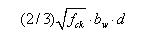
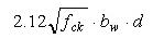
Vu : Maximum factored shear force of the relevant member or section on the basis of examining all the load combinations at the 5 sectional locations.
Rat-V
: Ratio of the factored shear force (Vu)
to the design shear strength ( design strength is unsatisfactory even if the rebar quantity is increased to the maximum rebar ratio or the minimum rebar spacing for the relevant brace section.
As-H : Reinforcing steel section area (LengthUnit 2 / LengthUnit x 100 ) required for the shear force calculated by the program, with the lower bound being the minimum rebar quantity specified in the codes.
H-Rebar : Shear rebar placement spacing expressed in terms of As-H using the sub-rebar standard sizes entered by the user.
The following are displayed for H-Rebar based on the automatic design results :
= "#xx @yyy", "Dxx @yyy"
xx is the designated standard rebar size, yyy is the rebar spacing (unit: inch).
= "Failure"
Note
Common Control
The updated rebar data are used for strength verification.
Redesign the selected members. When the redesign is executed from the results displayed by section properties, all the members attributed to the same sections are included. This option can be used even when the rebar splice data is changed.
Note When modifying the design parameters ('Modify Concrete Material', etc.) that can affect all the design results, this option cannot be used since the design results will be deleted.
Note In all the Design Result Dialogs & Code Checking Result Dialogs, the Graphic Reports can be saved in a batch.
The design results "Sorted by Member" support the detail calculations.
The forces corresponding to the maximum rebars are produced when "Sorted by Property" is selected, representing all the members of same properties.
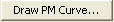
Plot the results and the corresponding P-M interaction diagram applicable for the factored axial force and biaxial moments.
All: Produce all the auto-designed results in the Design Results dialog box
OK: From the auto-designed results, display only the design results that have met the design requirements (OK), in the Design Results dialog box
NG: From the auto-designed results, display only the design results that have not satisfied the design requirements (NG), in the Design Results dialog box
| ||||||||||||||||||||||||||||||||||||||||||||||||
|
| ||||||||||||||||||||||||||||||||||||||||||||||||
 state for convenience)
 Pn
Pn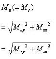

 exceeds
 (Refer to
the Note below) in
(Refer to
the Note below) in
 : Display the applicable
code for automatic design.
: Display the applicable
code for automatic design.
 : Display the unit system
selected by the user.
: Display the unit system
selected by the user.
 : Update the rebar quantity
for each property type in the rebar design data.
: Update the rebar quantity
for each property type in the rebar design data. : Select all members
 : Cancel the selection
of all members
: Cancel the selection
of all members
 : Display simplified
automatic design results
: Display simplified
automatic design results : Produce the automatic
design results in summary calculations for the selected members.
: Produce the automatic
design results in summary calculations for the selected members.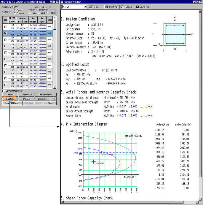
 : Produce the automatic
design results in detail calculations for the selected members.
: Produce the automatic
design results in detail calculations for the selected members.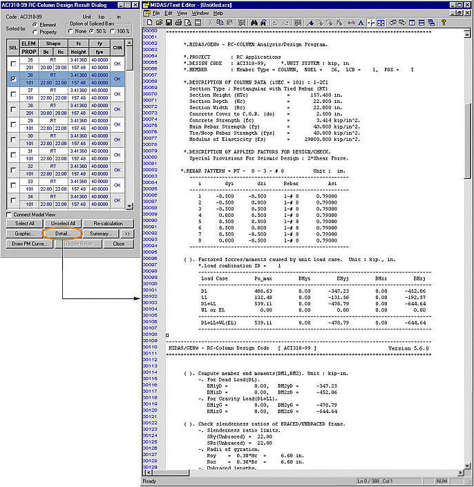
 : Produce the summary
list of automatic design results for the selected members.
: Produce the summary
list of automatic design results for the selected members.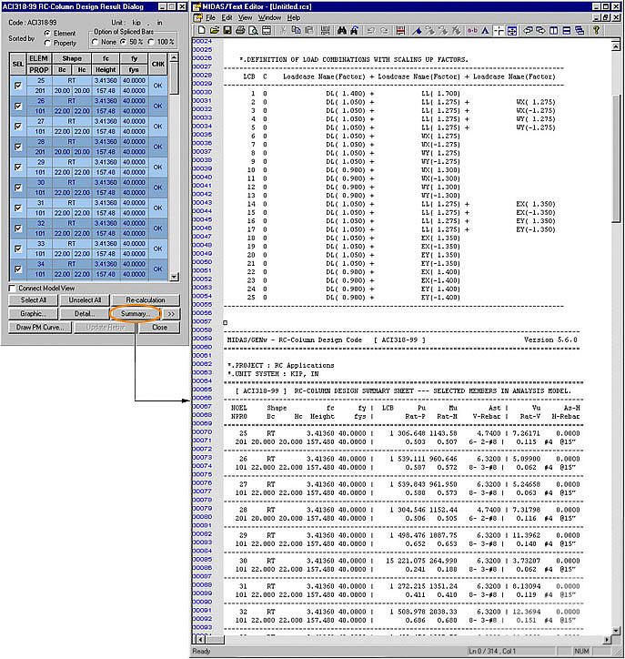
 : Check in the option
to select and highlight the selected members in Model View.
: Check in the option
to select and highlight the selected members in Model View. : Close the dialog box