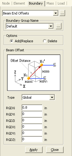
Beam End Offsets
Define Rigid End Offset Distance or take into account the Joint Eccentricity with respect to GCS or element's local coordinate system at both ends of beam elements.
Beam End Offsets can be specified in conjunction with (Beam End Release).
Note
This function cannot be used with truss elements and can be applied to beam elements only. If truss elements are changed into beam elements (Model > Elements > Change Element Parameters), Beam End Offset can be applied. To describe the behavior of truss elements, rotational degrees of freedom of beam elements should be released. This can be done using Model > Boundaries > Beam End Release.
From the Main Menu select Model > Boundaries > Beam End Offsets.
Select Geometry > Boundaries > Beam End Offsets in the Menu tab of the Tree Menu.
Click ![]() to the right of Beam End Offsets : Display the Beam End Offsets Table
to the right of Beam End Offsets : Display the Beam End Offsets Table
 Boundary Group Name
Select a Boundary Group in which the specified boundary condition is included. Select "Default" if Group assignment is unnecessary. Click ![]() to the right to prompt the "Define Boundary Group" dialog box to add, modify or delete Boundary Groups.
to the right to prompt the "Define Boundary Group" dialog box to add, modify or delete Boundary Groups.
Options
Add/Replace: Enter or replace end offset distance and joint eccentricity for selected beam elements
Delete: Delete previously entered end offset distances and joint eccentricities for selected beam elements
When Type = 'Element'
|
|
|
Enter the end offset distance with respect to element's local x-direction.
RGDi: End offset distance in the element's local (+) x-direction at N1 end
RGDj: End offset distance in the element's local (-) x-direction at N2 end
Positive values must be entered for RGDi and RGDj. The beam element length will be then adjusted to reflect RGDi and RGDj.
Element length: L = L0 - (RGDi + RGDj)
Where, L0: original length of beam element (distance between the ends, N1 and N2)