Structure Type
Enter the type of and the basic data for structural analysis.
From the Main Menu select Model > Structure Type.
Select Configuration > Structure Type from the Menu tab of the Tree Menu.
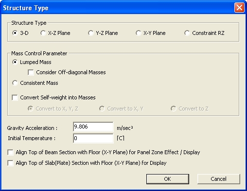
Structure Type dialog box
 Structure Type
Select an option as to whether the analysis is to be carried out in 3-D or 2-D.
3-D: 3-D structural analysis
X-Z Plane: 2-D analysis in GCS X-Z plane
Y-Z Plane: 2-D analysis in GCS Y-Z plane
X-Y Plane: 2-D analysis in GCS X-Y plane
Constraint RZ: 3-D analysis constraining rotational degree-of-freedom about GCS Z-axis
Note
Usage
of Structure Type option
Mass Control
Parameter
Define mass type as Lumped Mass or Consistent Mass.
The user can consider whether to convert the model self-weight into lumped/consistent masses for dynamic analysis using the Convert Self-weight into Masses option.
Lumped Mass : Convert into lumped masses.
The total mass of an element is directly distributed to the nodal points of an element. In general, only the diagonal terms of the lumped mass matrix are considered for mass calculations. Off-diagonal terms are zero.
Consider Off-diagonal Masses : When this option is checked on, all terms including off-diagonal terms in the lumped mass matrix are considered for mass calculations. The accuracy of results increases with a full lumped mass matrix, but the analysis time may increase. When Consider Off-diagonal Masses option is checked off, the matrix is considered as a vector.
When a section offset is considered, a node will be generated at the offset location and the loads, boundary conditions, masses, etc. to be applied to the node will be entered to the node at the offset location. However, structural characteristics related to elements (e.g., element stiffness, loads to be applied to the elements, masses converted from self-weight of elements, etc.) have to be entered at the centroid of a section. If this option is checked, masses converted from self-weight of elements are entered at the centroid of a section. Nodal mass and nodal load, which is entered at the node and has no relation to elements, will be entered at the offset node.
Note 1 Off-diagonal Masses can be reflected in the time history analysis.
Note 2 When Mass Offset is used, only Lanczos method will be supported for the Eigenvalue analysis.
Note 3 When Mass Offset is used, the Section Offset of a beam element will be taken into account. Mass Offset will be effective only in beam elements.
Consistent Mass : Convert into distributed masses.
Consistent Mass is calculated with the shape function used to derive the stiffness matrix. Off-diagonal mass terms are considered and, unlike the lumped mass, the inertia coupling effect is considered. Therefore, results using the consistent mass is more accurate than the lumped mass, however it takes more time for numerical computation.
Consistent masses can be applied only when the "Lanczos" option is selected in the Eigenvalue Analysis Control.
Note 1 Consistent Mass can be reflected in the time history analysis.
Note 2 When Consistent Mass is used, only Lanczos method will be supported for the Eigenvalue analysis.
Convert Self-weight into Masses
Convert to X, Y, Z: Convert the self-weight into lumped masses in the GCS X, Y, Z-directions
Convert to X, Y: Convert the self-weight into lumped masses in the GCS X, Y-directions
Convert to Z: Convert the self-weight into lumped masses in the GCS Z-direction
Note Usage of Convert
Self-weight into Masses
Gravity acceleration
Enter the acceleration of gravity considering the unit system in use.
Initial Temperature
Enter the initial temperature required for a thermal stress analysis.(Refer to Load > System Temperature or Nodal Temperature)
Align Top of
Beam Section with Floor (X-Y Plane) for Panel Zone Effect/Display
Align the tops of line elements in the GCS X-Y plane such that their top elevations line up at the floor level (nodal positions of columns) when reflecting rigid offsets or displaying the elements in the Model Window. (Refer to "Rigid Offset Distance")
Note
In order to see Panel Zone Effect applied, "Auto Calculate
Panel Zone Offset Distances" should be defined first in Model
> Boundaries > Panel
Zone Effect.
Align Top of
Slab (Plate) Section with Floor (X-Y Plane) for Display
Align the tops of plate elements in the GCS X-Y plane such that their top elevations line up at the floor level (nodal positions of columns) when displaying the elements in the Model Window.
Note
When the alignment options are not selected, the centerlines of the line and plate elements are shown to be connected to the column nodes.