Wind Loads
In midas Gen, the automatic data entry of wind loads according to various standards is applicable for common buildings where each story can be defined and can reasonably act as a rigid diaphragm. The following procedure is observed :
Model the structure.
The structure must be modeled so that the gravity acts in the direction opposite to the GCS Z-direction.
Use Building > Control Data to define the elevation of ground level in GCS Z-axis coordinate.
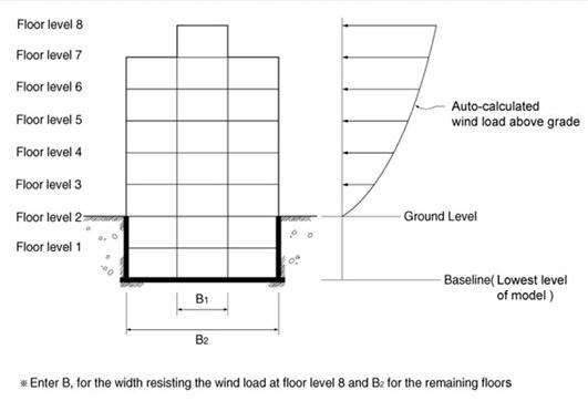
When the ground level is entered, the parts below this level are considered as underground stories and neglected in the wind load calculation. If the ground level is not specified, the lowest part of the modeled structure is assumed to be the ground level by default.
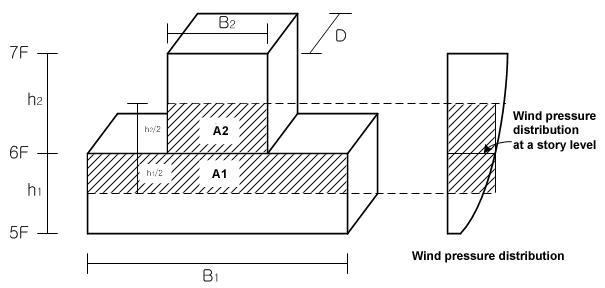
Use Story to define stories and their floor rigid diaphragm characteristics. Enter the application position of wind loads and the width of the story subjected to pressure to generate the wind load at each story.
It is recommended that ![]() be used to auto-generate the data necessary for
the stories and the application of wind loading. Where openings
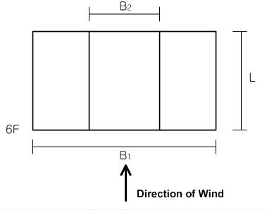
exist at a particular story, adjust the width of the wind pressure
area.
be used to auto-generate the data necessary for
the stories and the application of wind loading. Where openings
exist at a particular story, adjust the width of the wind pressure
area.
Once the floor diaphragm is defined in Story, the X-, Y-displacement degrees-of-freedom and the rotational degree-of-freedom about the Z-axis between all the nodes on the plane (plane parallel to the GCS X-Y plane) are constrained.
In addition, a part or all of the constrained nodes can be separated from the rigid floor diaphragm using Floor Diaphragm Disconnect.
Assign the wind load calculation standards in Wind Loads and enter the required data.
[Built-in wind load calculation standards in midas Gen]
Once the data required for the calculation
of wind loads are defined, auto-calculate wind loads for each
story in connection with the story data generated in Story. Use
![]() to verify the auto-calculated
wind loads.
to verify the auto-calculated
wind loads.
[Wind load generation...]
From the Main Menu select Load > Wind Loads.
Select Static Loads > Wind Loads in the Menu tab of the Tree Menu.
Access Wind Loads to activate the
dialog box defining the wind loads. Click ![]() to display the dialog box shown below.
to display the dialog box shown below.
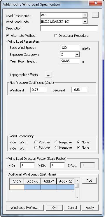
Add/Modify Wind Load Code dialog box
 Load Case Name
Select the load case name to be associated
with the wind load. Click ![]() to the
right to enter or modify new load cases.
to the
right to enter or modify new load cases.
Wind Load Code
Select the standards to be applied to the wind load calculation.
IBC 2012(ASCE7-10): International Building Code 2012
IBC 2009(ASCE7-05): International Building Code 2009
IBC 2000(ASCE7-98): International Building Code 2000
UBC (1997): UBC 97 standards
ANSI (1982): ANSI standards
NBC (1995): National Building Code of Canada
Eurocode-1 (1992): Basis of Design and Actions on Structures
BS6399 (1997): British Standard 6399 Loading for buildings
IS875 (1987): Indian Standard
Taiwan (2002): Taiwan Building Code
Description
Enter a short description.
Wind Load Parameters
Enter the parameters to be applied to the wind load calculation.
Wind Load Direction Factor
Enter the loading direction and the magnitude of wind load to be applied.
X-Dir.: Scale factor to be applied in GCS X-direction
Y-Dir.: Scale factor to be applied in GCS Y-direction
Z-Rot.: Scale factor to be applied in torsion about GCS Z-direction
Note
It is activated only when Japan (Arch, 2004) is selected.
Additional Wind Loads
Enter additional wind loads that the auto-calculation does not take into account.
Press ![]() to enter
the stories to apply additional wind loads and the magnitudes
for each direction.
to enter
the stories to apply additional wind loads and the magnitudes
for each direction.
![]() : Display Tables and Graphs in a spreadsheet form for each loading
direction and component of the auto-calculated wind loads.
: Display Tables and Graphs in a spreadsheet form for each loading
direction and component of the auto-calculated wind loads.
Component: Assign the wind loading direction for a graphic display
Select Profile: Select the items to be displayed
Story Force
Story Shear
Overturning Moment
![]() : Display a spreadsheet Text Output file showing the wind load
calculation process.
: Display a spreadsheet Text Output file showing the wind load
calculation process.
Text Editor is automatically executed.
![]() : Apply the auto-calculated wind loads to the model.
: Apply the auto-calculated wind loads to the model.
Note
Refer to the relevant code for details regarding
the wind
load calculation.