Define Plane Load Type
Define types and magnitudes of Plane Loads. The Plane Loads defined by this feature are applied to the structure through the Assign Plane Loads feature. The Plane Loads can be applied to any specific locations on plate and solid elements, which constitute an analysis model. This capability alleviates the cumbersome tasks of locating nodes where loads are applied. The defined loads are converted into nodal loads based on the stiffness of the plate and solid elements and applied to the contiguous nodes.
From the Main Menu select Load > Define Plane Load Type.
Select Static Loads > Define Plane Load Type in the Menu tab of the Tree Menu.
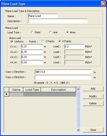
Plane Load Type dialog box
![]() Click
Click ![]() to initially define or add plane loads after providing the data below. Click
to initially define or add plane loads after providing the data below. Click ![]() or
or ![]() to change or eliminate the previously defined plane loads respectively.
to change or eliminate the previously defined plane loads respectively.
 Plane Load Type & Description
Name: specify the name of Plane Load
The Assign Plane Loads feature refers to the Name when the defined plane loads are applied to the analysis model. Generally, true load types are specified, namely, Office, Equipment, etc.
Description: description of the name
Plane Load
Define the load type, location and magnitude, which will be loaded on the plane defined in the Loading Plane field of the Assign Plane Loads dialog box.
Load Type
Specify the load type among Point, Line and Area loads.
Point Load
x, y: coordinates of the point loads in the plane coordinate system, which is defined by the origin and x-y axes specified in the Loading Plane field of the Assign Plane Loads dialog box.
Force: magnitudes of concentrated loads
Moment: magnitudes of concentrated moments
Line Load
Uniform: Check if the line load is uniformly distributed
Type: specify the type of the line load
![]() x1, y1: starting coordinates of the line load on the plane coordinate system
x1, y1: starting coordinates of the line load on the plane coordinate system
![]() x2, y2: ending coordinates of the line load on the plane coordinate system
x2, y2: ending coordinates of the line load on the plane coordinate system
Load: magnitude of force/moment at each location
Area Load
Uniform: check if the plane load is uniformly distributed
Point: number of points defining the loaded plane
![]() x1, y1: coordinates of the first point defining the loaded area
x1, y1: coordinates of the first point defining the loaded area
![]() x2, y2: coordinates of the second point defining the loaded area
x2, y2: coordinates of the second point defining the loaded area
![]() x3, y3: coordinates of the third point defining the loaded area
x3, y3: coordinates of the third point defining the loaded area
![]() x4, y4: coordinates of the fourth point defining the loaded area
x4, y4: coordinates of the fourth point defining the loaded area
Load: magnitudes of loads at each corner of the loaded area
Note 1
The corners of a polygon defining the loaded area must be consistently specified either clockwise or counterclockwise.
Note 2
We may find it more convenient to coincide the plane coordinate system with the global coordinate system or user coordinate system, which allows us to use the mouse editor and point grids to enter the last loaded location.
Copy x-Direction
Copy the defined plane load in the x-direction by specifying copy distances
Copy y-Direction
Copy the defined plane load in the y-direction by specifying copy distances
Click ![]() to include the defined plane load in the list. Click
to include the defined plane load in the list. Click ![]() to change the entered data and
to change the entered data and ![]() to eliminate previously defined plane loads.
to eliminate previously defined plane loads.