Story Shear Force Ratio
Story Shear Force Ratios of the lateral force resisting members can be checked or modified in a spreadsheet format table.
When "Story Shear Force Ratio>Consider Story Module" is checked in the "Model/Building/Control Data", accurate shear forces can be obtained for the story having the overlapping Module.
When Modules are defined in Results > Result Tables > Story > Define Module, the Module data is displayed in the first column of the table.
"Story Shear Force Ratio" in "Model/Building/Control Data" must be checked for this function, which is checked as the Default.
Note
If Pushover analysis has been performed, Story Shear Force ratios
of members resulting from the Pushover analysis can be checked.
The distribution ratios are expressed in terms of resistance by column members (Frame_Beam), brace menbers (Frame_Truss) and shear wall members (Wall).
Note
If the structure contains Planar and Solid elements, the ratios
are classified separately into Planar and Solid.
Table Tool in midas Gen offers a variety of powerful built-in functions. Refer to the following items for detail directions:
Usage of Table Tool
Terminology
Familiarize with Usage
Basic directions (Cell motion, selection, size control, etc.)
Data manipulation (Add, delete, modify data, etc.)
Copy/Paste data using clipboard
Supplementary Table functions
Table Sorting
Table format setting
Auto-fit column width
Graph printing
Supplementary functions by Table types
Node/Element Table
Results Table
From the Main Menu select Results > Result Tables > Story > Story Shear Force Ratio.
Select Result Tables > Story > Story Shear Force Ratio in the Tables tab of the Tree Menu.
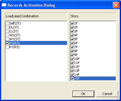
Select static load cases from the Records Activation Dialog, and click the [OK] button.
Refer to Usage of Table Tool and check the following data:
![]() When Modules are not defined
When Modules are not defined
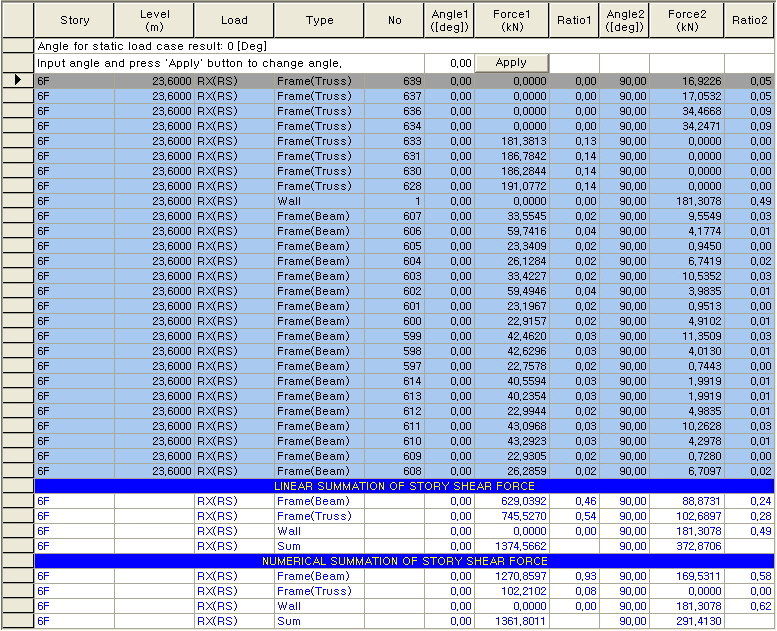
Story: Story ID
Level: Story elevation level
Load: Static lateral load (Static Seismic Load, Wind Load)
Type: Element type
Frame(Beam): Column member
Frame(Truss): Brace member
Note
Brace members(Frame_Truss) contain Truss, Tension only, Compression only elements.
Wall: Shear wall member
No: Element number
Angle 1([deg]): Angle of a shear force component.
Force 1(tonf): Shear force in the direction of Angle 1
Ratio 1: Shear force distribution ratio in the direction of Angle1
Angle 2([deg]): Angle1 + 90°
Force 2(tonf): Shear force in the direction of Angle 2
Ratio 2: Shear force distribution ratio in the direction of Angle2
Input angle and press 'Apply' button to change angle: Input the angle of a shear force component (Angle 1), and click the
![]() button. You can then observe the shear forces and distribution
ratios in the direction of the corresponding input angle.
button. You can then observe the shear forces and distribution
ratios in the direction of the corresponding input angle.
Note 1
Angle1 determines the reference direction to calculate the shear force. If Angle 1 is consistent with the loading direction, the story shear is consistent with the inputted load, and the distribution ratios, which are contributed by the members, can be checked.
Note 2
The story shear force due to response spectrum loads is obtained by combining the story shear forces of each mode using the modal combination method.
Frame and Wall
in the Summation of Story Shear Force (![]() ) represent
the summation of all shear forces of Frame and Wall respectively
for the corresponding story. Therefore, the summation of ratios
of Frame and Wall would be always 1.0.
) represent
the summation of all shear forces of Frame and Wall respectively
for the corresponding story. Therefore, the summation of ratios
of Frame and Wall would be always 1.0.
![]() When
Modules are defined
When
Modules are defined
Module: Module name is defined in Define Module
Story: Story ID
Level: Story elevation level
Load: Static lateral load (Static Seismic Load, Wind Load)
Type: Element type
Frame(Beam): Column member
Frame(Truss): Brace member
Note
Brace members(Frame_Truss) contain Truss, Tension only, Compression only elements.
Wall: Shear wall member
No: Element number
Angle 1 ([deg]): Angle of a shear force component.
Force 1 (tonf): Shear force in the direction of Angle 1
Ratio 1: Shear force distribution ratio in the direction of Angle1
Angle 2 ([deg]): Angle1 + 90?/p>
Force 2 (tonf): Shear force in the direction of Angle 2
Ratio 2: Shear force distribution ratio in the direction of Angle2
Input
angle and press 'Apply' button to change angle: Input the
angle of a shear force component (Angle 1), and click the ![]() button. You can then observe the shear
forces and distribution ratios in the direction of the corresponding
input angle.
button. You can then observe the shear
forces and distribution ratios in the direction of the corresponding
input angle.
Note 1
Angle1 determines the reference direction to calculate the shear
force. If Angle 1 is consistent with the loading direction, the
story shear is consistent with the inputted load, and the distribution
ratios, which are contributed by the members, can be checked.
Note 2
The story shear force due to response spectrum loads is obtained
by combining the story shear forces of each mode using the modal
combination method.
Frame and Wall in the Summation of Story Shear Force represent
the summation of all shear forces of Frame and Wall respectively
for the corresponding story. Therefore, the summation of ratios
of Frame and Wall would be always 1.0