Torsional Amplification Factor Table
This function calculates Torsional Amplification Factors to be applied to a torsionally irregular structure when an equivalent static analysis is carried out.
When "Story Shear Force Ratio>Consider Story Module" is checked in the "Model/Building/Control Data", accurate shear forces can be obtained for the story having the overlapping Module.
When Modules are defined in Results > Result Tables > Story > Define Module, the Module data is displayed in the first column of the table.
Table Tool in midas Gen offers a variety of powerful built-in functions. Refer to the following items for detail directions:
Usage of Table Tool
Terminology
Familiarize with Usage
Basic directions (Cell motion, selection, size control, etc.)
Data manipulation (Add, delete, modify data, etc.)
Copy/Paste data using clipboard
Supplementary Table functions
Table Sorting
Table format setting
Auto-fit column width
Graph printing
Supplementary functions by Table types
Node/Element Table
Results Table
From the Main Menu select Results > Result Tables > Story > Torsional Amplification Factor
Select Result Tables > Story > Torsional Amplification Factor in the Tables tab of the Tree Menu.
From Record Activation Dialog, select the load cases/combinations for which Torsional Amplification Factor will be calculated.
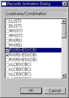
Record Activation dialog box
Refer to Usage of Table Tool and check the following data:
![]() When Modules are not defined
When Modules are not defined
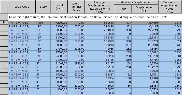
Load Case: Load case/Combination
Story: Story ID
Level: Story Elevation
Story Height: Story Height
1. Average Displacement of Extreme Points
1.2*Story Displacement: 1.2 times the average of the combined displacements of vertical members at corner (Extreme) points for the given loading condition.
2. Maximum Displacement
Node: Node number at which the maximum displacement takes place at the corresponding story for the given loading condition
Story Displacement: Combined displacement at the Node associated with the maximum displacement
3. Torsional Amplification Factor
Torsional Amplification Factor = The square of the value of "Story Displacement of Maximum Displacement" divided by "1.2*Story Displacement of Average Displacement of Extreme Points"
![]() When Modules are defined
When Modules are defined
The Module column is generated only when the Modules are defined. Torsional amplification factors for each Story and Module are calculated as per the following Note.
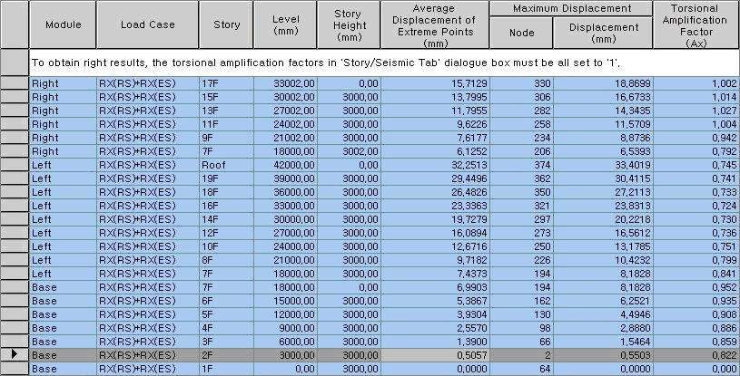
Module: Module name is defined in Define Module
Load Case: Load case/Combination
Story: Story ID
Level: Story Elevation
Story Height: Story Height
1. Average Displacement of Extreme Points
1.2*Story Displacement: 1.2 times the average of the combined displacements of vertical members at corner (Extreme) points for the given loading condition.
2. Maximum Displacement
Node: Node number at which the maximum displacement takes place at the corresponding story for the given loading condition
Story Displacement: Combined displacement at the Node associated with the maximum displacement
3. Torsional Amplification Factor
Torsional Amplification Factor = The square of the value of "Story Displacement of Maximum Displacement" divided by "1.2*Story Displacement of Average Displacement of Extreme Points"