Wall Opening
Define openings in a wall element. By specifying wall opening size and location, wall elements are vertically divided and beam elements are generated at the top and bottom of a opening.
From the Main Menu select Node/Element > Elements > Wall Opening.
![]() Start
Node Number
Start
Node Number
Assign
a number to the new starting node created together with new elements
in the Model Window. This number is auto-set to the largest node
number in use +1. To modify this item, click ![]() and select an option to specify a desired number.
and select an option to specify a desired number.
![]() Opening
Type
Opening
Type
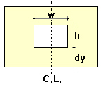
Direction: Select a reference point to define opening size and position.
i->j
|
j->i
|
Middle
|
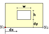
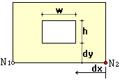
Distance
dx: Horizontal distance from the reference point to the near most edge of an opening
dy: Vertical distance from the reference point to the near most edge of an opening
Opening Size
w: Width of an opening
h: Height of an opening
Subdivide Frame Elements
If this option is selected, the line elements on the periphery of the wall element are divided according to the opening width.
Merge Duplicate Nodes
Merge
overlapping nodes to single nodes if new nodes coincide with existing
nodes. Click ![]() to
modify the Merging Tolerance.
to
modify the Merging Tolerance.
Note.
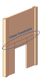
Once wall opening is defined, wall element will be vertically divided and additional beam elements are automatically generated at the top and bottom of the opening. If "Auto Constraint for Wall Elements Connectivity" option is checked on in Main Control Data, "Linear Constraint" will be automatically considered for the connectivity with the top and bottom of the connected elements.
|