Local Direction Force Sum
Local Direction Force Sum provides internal forces on a selected plane in plate or solid elements. The resultant forces and the acting point are calculated on the basis of all the nodal forces included in the selected plane. Once a detail analysis is carried out for a specific part of the structure, this function conveniently calculates the member forces for structural design.
From the Main Menu select Results > Detail > Local Direction Force Sum.
 Mode
Mode
Assign the method of selecting the subject plane that includes the nodes where internal forces are to be combined.
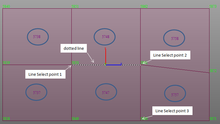
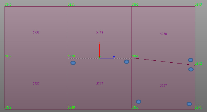
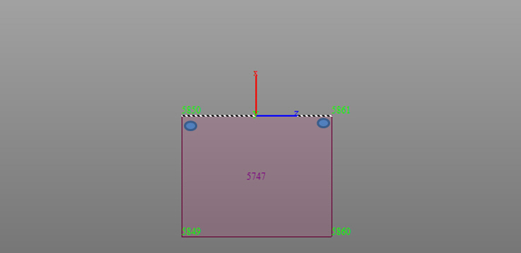
Line Select : Define a plane within beam, plate, and solid elements. The plane is selected by defining a straight line passing through the beam, plate, and solid element nodes.
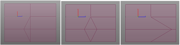
Polygon Select : Define a plane within beam, plate, and solid elements. The plane is selected by Polygon Select.
Type of element
Check on desired element types to be included in the resultant force calculation. For Line Select mode, beam and plate elements can be selected. For Polygon Select, beam, plate, and solid elements can be selected.
Load Case
Select a desired load case or load combination. Envelop Type load combination cannot be selected.
Tolerance
Tolerance defining a line or polygon
Coordinate Input
Positions: Enter the GCS coordinates of the points necessary to assign a line or polygon
Note
Enter the coordinates of the points, or click the entry field and
the desired points to automatically enter the coordinates. To
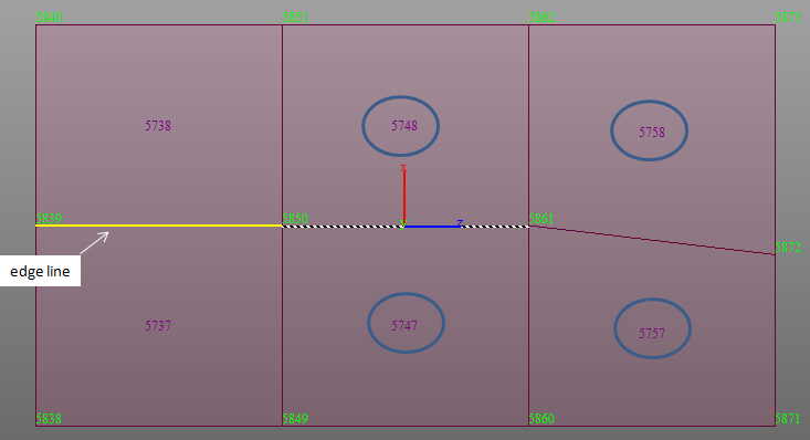
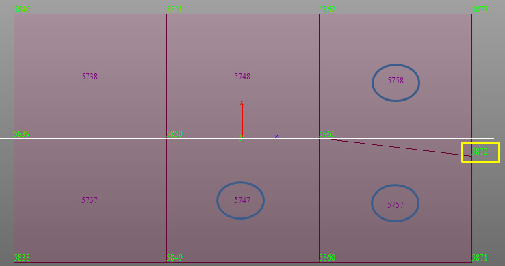
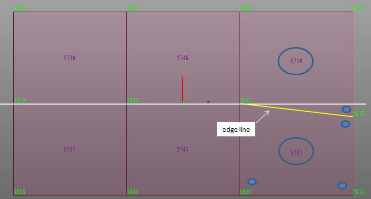
select Plate Edge Line Select, enter the coordinates of the two
points defining a line and additionally enter the coordinates
of the 3rd point that defines the direction as to which side of
the elements
are to be considered.
Vector: Enter a vector to define the z-axis of the local coordinate system to which Result Output is referenced
Note
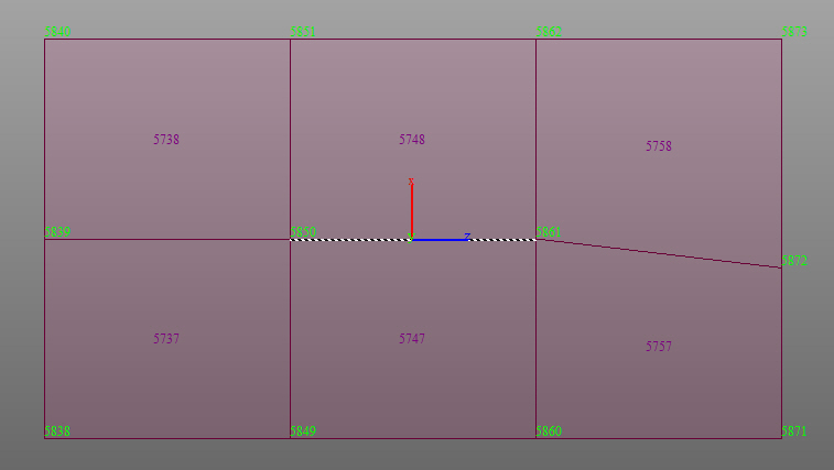
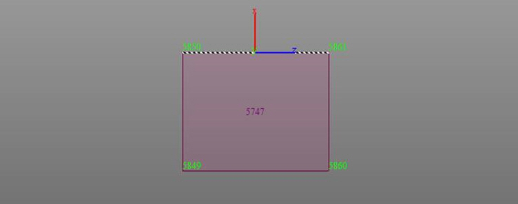
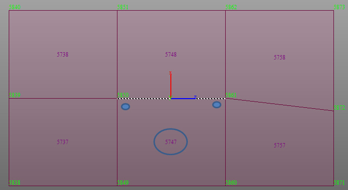
The sum of nodal internal forces for each element is calculated at the center
of the selected plane section with respect to the local coordinate
system.
When defining a polygon, the local axes are determined by the entry sequence of the coordinates of the points (right hand rule).
If the z-vector is not defined, the direction from the 1st to 2nd point of the polygon becomes the local z-axis by default.
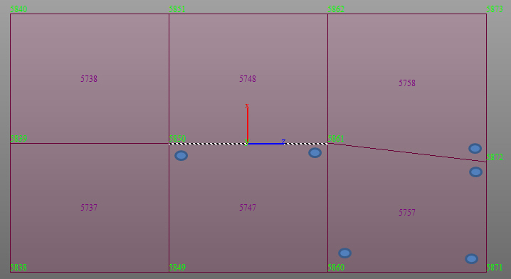
Click ![]() in the Local Direction Force Sum dialog box to review
the local
coordinate axes displayed at the centroid.
in the Local Direction Force Sum dialog box to review
the local
coordinate axes displayed at the centroid.
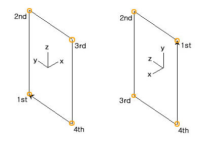
Local coordinate system convention (when z-vector is not specified)
Resultant Force Location
Auto-Calc.: By default, resultant forces are calculated at a dimension center. When only plate elements exist, the resultant force location is automatically calculated as a gravity center.
User Input: Input the desired coordinates in GCS to calculate the resultant force. This option is useful when calculating the resultant force for more than two types of elements.
Result Output
Produce the position of the centroid of the defined section and the sum of internal forces for each direction.
![]() Name
Name
Define a name, which will be used to register in a list of centroid locations of defined sections and internal force sums for each direction.
![]() :
Calculated results are produced in a text file. Using this function
allows us to save multiple locations where we wish to find the
sums of internal member forces, which can be output in a text
file.
:
Calculated results are produced in a text file. Using this function
allows us to save multiple locations where we wish to find the
sums of internal member forces, which can be output in a text
file.
![]() ;
Calculated results are produced in a table . Using this function
allows us to see multiple locations where we wish to find the
sums of internal member forces, which can be output in a table.
;
Calculated results are produced in a table . Using this function
allows us to see multiple locations where we wish to find the
sums of internal member forces, which can be output in a table.
On clicking the Table Output option, the records activation dialog box is displayed, from where you can select the load cases for which to display the local direction force sum in a tabular format.
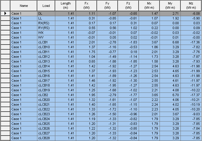
Local direction Force Sum Table Output
Name: Name which is used to register in a list of centroid locations of defined sections and internal force sums for each direction.
Load: Load Case/Combination
Fx: Axial force
Fy: Shear force in the element's local y-direction
Fz: Shear force in the element's local z-direction
Mx: Torsional moment about the element's local x-axis
My: Bending moment about the element's local y-axis
Mz: Bending moment about the element's local z-axis
![]() Revision of Gen 2015 (v1.1)
Revision of Gen 2015 (v1.1)