Story
Story is used to define the floor levels if the analysis model is a building. Because the positions of the stories are defined using the GCS Z-axis coordinates, the floor planes of the building must inevitably be parallel to GCS X-Y plane.
Story is used for the following purposes:
Assign wall combination numbers to the wall elements entered in the analysis model.
Define stories to apply the auto-calculated lateral forces as story forces. (Refer to "Wind Load" and "Static Seismic Load")
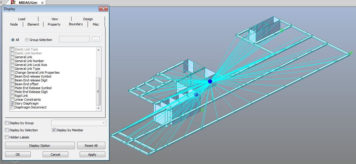
Consider automatically rigid diaphragm action and specify diaphragm masses at the relevant stories. (Refer to "Floor Diaphragm Masses")
After analysis, Story is used to classify and arrange results data such as story drifts, input loads and self-weights by stories. (Refer to "Story Drift", "Story Weight Table", "Story Load Table")
From the Main Menu select Structure > Building > Control Data > Story.
Shortcut key: [F10]
![]() Auto Generation Story Data
Auto Generation Story Data
Use the Table Entry function to directly
enter the story data in the Table or click ![]() .
.
 Ground Level
The ground level is expressed by the coordinate of the GCS Z-axis. The stories from the Base to the ground level are assumed as underground stories and designated as 'B1', 'B2'... during the auto-generation of story data.
Direct Entry Method
of Story Data in Table
Refer to "Usage of Table Tool"
in the Story Entry Table to enter the following data:
Terminology
Familiarize with Usage
Basic directions (Cell motion, selection, size control, etc.)
Data manipulation (Add, delete, modify data, etc.)
Copy/Paste data using clipboard
Supplementary Table functions
Table Sorting
Table format setting
Auto-fit column width
Graph printing
Supplementary functions by Table types
Node/Element Table
Results Table
The command supplies 3 Table dialog boxes related to stories and the data entries for each dialog box are as follows :
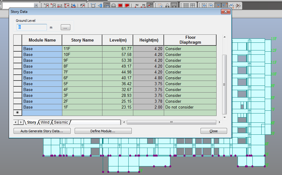
Story tab
Module name: Modules for the building structure, such as a twin tower. Click [Define Module] button to define module data.
Story Name
Level : Story height (elevation)
Height : Floor to floor height
Floor Diaphragm : Assign Floor Rigid Diaphragm to the relevant story. This function constrains Dx, Dy and Rz to the relevant story.
Note 1
If "Do not consider" is selected for Floor Diaphragm and Membrane Type of wall is defined, Singular Warning message is displayed when the analysis is carried out. This is because Membrane Type of wall does not have out-of-plane stiffness. It can be resolved by changing the Membrane Type into Plate Type.
Note 2
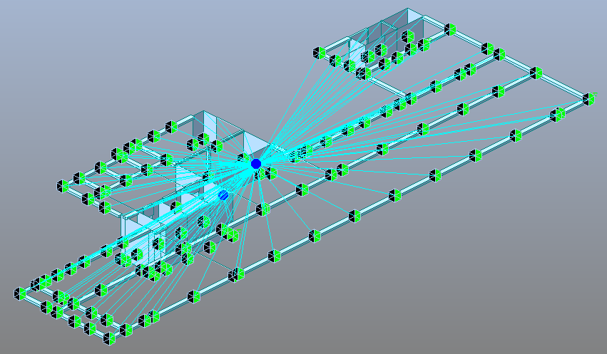
If Floor Diaphragm is considered, all masses of the relevant story are lumped into Mass Center. The mass data lumped into Mass Center can be checked from Query> Story Mass Table.
Note 3
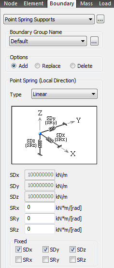
When a Support condition (3 translational degrees of freedom and 3 rotational degrees of freedom restrained) is assigned to a certain node on Floor Diaphragm, the degrees of freedom overlapping with Floor Diaphragm are automatically released.
Note 4
In case of stepped slabs, consider Floor Diaphragm to each slab and define Elastic Link-Rigid Type to the slab gap.
Wind tab
Name : Story name
Floor Width X-Dir. : Effective width of the building in X-axis, subjected to GCS Y-direction wind load
Floor Width Y-Dir. : Effective width of the building in Y-axis, subjected to GCS X-direction wind load
Floor Center Xc : Coordinate of the position in GCS X-direction, to which the wind load is applied
Floor Center Yc : Coordinate of the position in GCS Y-direction, to which the wind load is applied
Seismic tab
Name : Story name
Eccentricity X - Dir.
Accidental eccentricity distance in X-direction to calculate the accidental eccentricity moments due to the seismic loads at each story in GCS Y-direction when the equivalent static seismic load is calculated
Eccentricity Y - Dir.
Accidental eccentricity distance in Y-direction to calculate the accidental eccentricity moments due to the seismic loads at each story in GCS X-direction when the equivalent static seismic load is calculated
Auto-generate story
data
Click ![]() to auto-generate
the story, wind and seismic table data using the geometric data
of the building.
to auto-generate
the story, wind and seismic table data using the geometric data
of the building.
Note
midas Gen auto-generates story data based on the entered nodal
coordinates. midas
Gen assumes the Z-coordinates of all the entered nodes as story
levels and includes them in the Selected List. Click ![]() before clicking [OK] to exclude the levels
not required from the Selected List and move to the Unselected
List.
before clicking [OK] to exclude the levels
not required from the Selected List and move to the Unselected
List.
Include Seismic Accidental Eccentricity
When a static seismic load needs to be automatically calculated, check on the box to consider Accidental Eccentricity for torsional moment. The magnitude of the eccentricity is specified in percentage relative to a Plan Dimension.
Define Module
Click 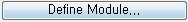 to assign
stories to each module for twin towers.
to assign
stories to each module for twin towers.
Module Name: Specify a Module Name.
Note
Define Module Names considering that Story Result Tables are generated in an ascending order or a descending order.
Select Stories
Start Story: Specify the lowermost story included in a module.
Include: Check on to include the currently selected story. For example, when start story is "2nd floor" and "Include" option is not selected, the module will included from "3rd floor".
End Story: Specify the uppermost story included in a module.
Include: Check on to include the currently selected story. For example, when end story is "5th floor" and "Include" option is not selected, the module will included up to "4th floor".
Define Story Region: Select a check box to activate [Define Story Region] button. This button shall be used for defining a region of each module. For example, in order to define the left tower in the figure below, specify Start Story as 2F and End Story as 5F with defining left tower region in the model view by mouse clicking. In order to define modules for twin tower, Story Region must be defined.
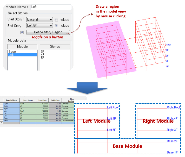
Module Data: Display Name & No. of Stories for the defined Modules.
![]() Revision of Gen 2015 (v1.1)
Revision of Gen 2015 (v1.1)
Q1. I get a warning in my model which is disturbing. It's seem to me that it's not affecting the results. When I run the analysis this warning appears. It appears for almost all supports placed on walls. Will it affect my analysis and what can I do to get rid of the warning? Command Message (50+ similar messages): [Warning] Constrained degrees-of-freedom at Slave nodes are automatically released. Node = 1552. DOF component = Y - Displacement