General Link Properties
Add, modify or delete the properties of general link elements.
General Link elements are used for modeling damping devices, base isolators, compression or tension-only elements, plastic hinges, soil springs, etc. General Link elements can be assigned linear and nonlinear properties using spring properties.
The procedure for boundary nonlinear dynamic analysis is shown below.
|
Procedure |
Menu |
|
1. Define material properties |
Model>Properties>Material... |
|
2. Define section properties |
Model>Properties>Section... |
|
3. Create elements |
Model>Elements>Create Elements... |
|
4. Define general link properties - Linear properties - Nonlinear properties |
Model>Boundaries>General Link Properties... |
|
5. Assign general link |
Model>Boundaries>General Link... |
|
6. Define boundary conditions |
Model>Boundaries>... |
|
7. Enter the static loads |
Load>Self Weight... Load>Assign Floor Loads... |
|
8. Enter masses |
Model>Structure Type... Model>Masses... |
|
9. Enter the time history loads 1) Generate time history load for vertical (gravity) loads - Define Time History Load Case - Define Time Forcing Functions (Normal type) - Enter Time Varying Static Load 2) Generate time history load for seismic loads - Define Time History Load Case - Define Time Forcing Functions (Earthquake record) - Enter the ground acceleration |
Load>Time History Analysis Data> Time History Load Cases... Time Forcing Functions... Time Varying Static Load... Ground Acceleration... |
|
10. Enter Eigenvalue Analysis Control (Ritz Vector) |
Analysis>Eigenvalue Analysis Control... |
|
11. Perform analysis |
Analysis>Perform Analysis... |
|
12. Check analysis results - Displacement / Velocity / Acceleration - Force diagrams - Stresses - Time history graphs of general links - Story Drift |
Results>Time History Results> Disp/Vel/Accel... Force Diagram (Beam/Truss/General Link)... Stress (Beam/Truss)... Time history graph... Results>Result Tables>Story>Story Drift (Time History Analysis) |
From the Main Menu select Boundary > Link > General Link > General Link Properties.
![]() To enter or add new properties of general link elements, click the
To enter or add new properties of general link elements, click the ![]() button.
button.
![]() To modify the properties of general link elements already defined, select a name from the list of General Link Properties, click the
To modify the properties of general link elements already defined, select a name from the list of General Link Properties, click the ![]() button and change appropriate data entries.
button and change appropriate data entries.
 Name
Name
Enter the name for which the properties of nonlinear link elements will be defined.
Application Type
Select the type of general link element. The types applied to analysis are largely classified into Element Type and Force Type.
Element Type: The Element Type general link element directly reflects the nonlinear behavior of the element by renewing the element stiffness matrix in the process of analysis.
Force Type: The Force Type general link element does not renew the element stiffness matrix. And rather, it reflects the nonlinear behavior indirectly by converting the member force calculated on the basis of the nonlinear properties into an external force.
Property Type
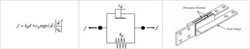
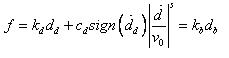
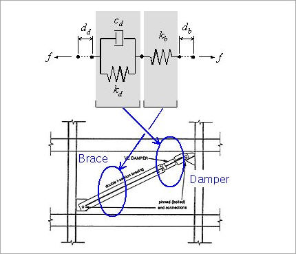
A specific link element is selected for an Application Type. The Element Type general link element provides 3 types; Spring, Linear Dashpot and Spring and Linear Dashpot. The Force Type general link element provides 6 types; Viscoelastic Damper and Hysteretic System used to represent damping devices, Lead Rubber Bearing Isolator and Friction Pendulum System Isolator used to represent base isolators, compression-only Gap element and tension-only Hook element.
Note
Among the Element Type General Link Elements, Spring Type (6 degrees of freedom : Dx, Dy, Dz, Rx, Ry & Rz) can be reflected in Pushover analysis. Also linear and inelastic analyses can be performed if the linear and inelastic hinge properties are assigned to the General Link Element. Inelastic hinge properties can be defined in Model > Property > Inelastic Hinge Property.
Description
Enter a brief description for the properties.
Self Weight
Enter the total weight of the general link. The entered self weight is by default equally divided between both ends of link. The ratio of self weight between i-end and j-end can be decided by the user.
Use Mass
The user may specify additional mass for the general link. The ratio of masses between i-end and j-end can be decided by the user.
Note
Self-weight of a General Link should be entered in Total Weight under Self Weight. Entered Total Weight will be applied to the direction assigned from Load>Self Weight for static analysis, and will be converted into nodal masses for dynamic analysis. In addition, check on Use Mass and input Total Mass to use specific mass separately from the nodal masses converted from Total Weight. However, if 'Do not Covert' is selected from Model>Structure Type> Conversion of Structure Self-weight into Masses, nodal masses converted from Total Weight and Total Mass will not be reflected in the analysis.
Linear Properties
Specify whether or not the individual springs of the 6 degrees of freedom of the general link element exist, and enter the corresponding effective stiffness.
Stiffness and Damping are entered for the Element Type, and Effective Stiffness and Effective Damping are entered for the Force Type general link element.
The stiffness or effective stiffness of a general link element is used for linear static and dynamic analyses. If modal superposition and direct integration methods are used in a linear time history analysis, the effective damping applies only when 'Group Damping' is selected for the structure. The Element Type general link element in a nonlinear time history analysis reflects the initial element stiffness based on the entered stiffness.
And if it relates to inelastic hinge properties, the stiffness is renewed in the analysis.
The Force Type general link element, on the other hand, retains the element stiffness based on the effective stiffness. Even if nonlinear properties are defined, the stiffness matrix remains unchanged. Especially, the effective stiffness in a boundary nonlinear time history analysis using the Force Type general link element represents imaginary stiffness to avoid rigid action in the algorithm. If the effective stiffness value is very large in nonlinear analysis, non-convergence may occur in the process of repetitive analyses, and as such an appropriate value should be entered. It is common practice to specify the initial stiffness of damping and isolator devices.
DOF: Check in the box to specify whether or not the springs of the 6 deformation degrees of freedom exist.
Dx, Dy, Dz: Translational deformation degrees of freedom in the x, y & z directions of the Element Coordinate System
Rx, Ry, Rz: Rotational deformation degrees of freedom about the x, y & z axes of the Element Coordinate System
Effective Stiffness
Coupled: Enter 6x6 coupled matrix for linear stiffness and damping.
Nonlinear Spring Properties
Check in the box to specify nonlinear spring properties for the 6 springs of the nonlinear link element by entering the parameters defining the nonlinear properties.
At this point, those springs that can be defined with nonlinear properties are limited to the degrees of freedom, which already have Linear Spring Properties. That is, the limitation applies to the degrees of freedom for which the DOF check boxes of Linear Spring Property are already checked in.
DOF: Check in the box to specify whether or not the nonlinear properties of the corresponding degrees of freedom exist.
Nonlinear Properties: Checking in the box prompts the dialog box. Enter the parameters defining the properties of the corresponding nonlinear springs.
Shear Spring Location
Check in the box to specify the locations of the shear springs.
The locations are defined by the ratios of relative distances from the starting node N1 to the total length. Dy and Dz represent the shear springs in the ECS y and z - axes respectively.
If the locations of the shear springs are specified, the end moments differ due to the shear forces (Difference in moments = shear force x member length). Conversely, if the locations of the shear springs are unspecified, the end moments are always equal without being affected by the shear forces.
![]() Entry of parameters pertaining to nonlinear properties of individual springs
Entry of parameters pertaining to nonlinear properties of individual springs
Enter the parameters defining the nonlinear properties of individual springs for 6 types of nonlinear link elements.